
Printed antenna

An antenna and straight line technology, which is applied in antennas, resonant antennas, antenna grounding devices, etc., can solve the problems of difficult coverage of 4G frequency bands, and the antenna form cannot guarantee bandwidth, etc., to improve high-frequency impedance characteristics, increase antenna efficiency, and broaden low-frequency The effect of bandwidth

Active Publication Date: 2013-12-04
HUAWEI DEVICE CO LTD
View PDF5 Cites 0 Cited by
  • Summary
  • Abstract
  • Description
  • Claims
  • Application Information

AI Technical Summary

Problems solved by technology

[0006] To sum up, for the printed antennas currently used in FMC products, the conventional antenna form cannot guarantee sufficient bandwidth, that is, it is difficult to cover the 4G frequency band while ensuring the 3G frequency band while taking into account GPS

Method used


Image

  • Printed antenna
  • Printed antenna
  • Printed antenna

Examples


Embodiment Construction

[0027] The technical solutions in the embodiments of the present invention will be clearly and completely described below in conjunction with the accompanying drawings in the embodiments of the present invention. Obviously, the described embodiments are only a part of the embodiments of the present invention, rather than all the embodiments. Based on the embodiments of the present invention, all other embodiments obtained by those of ordinary skill in the art without creative work shall fall within the protection scope of the present invention.

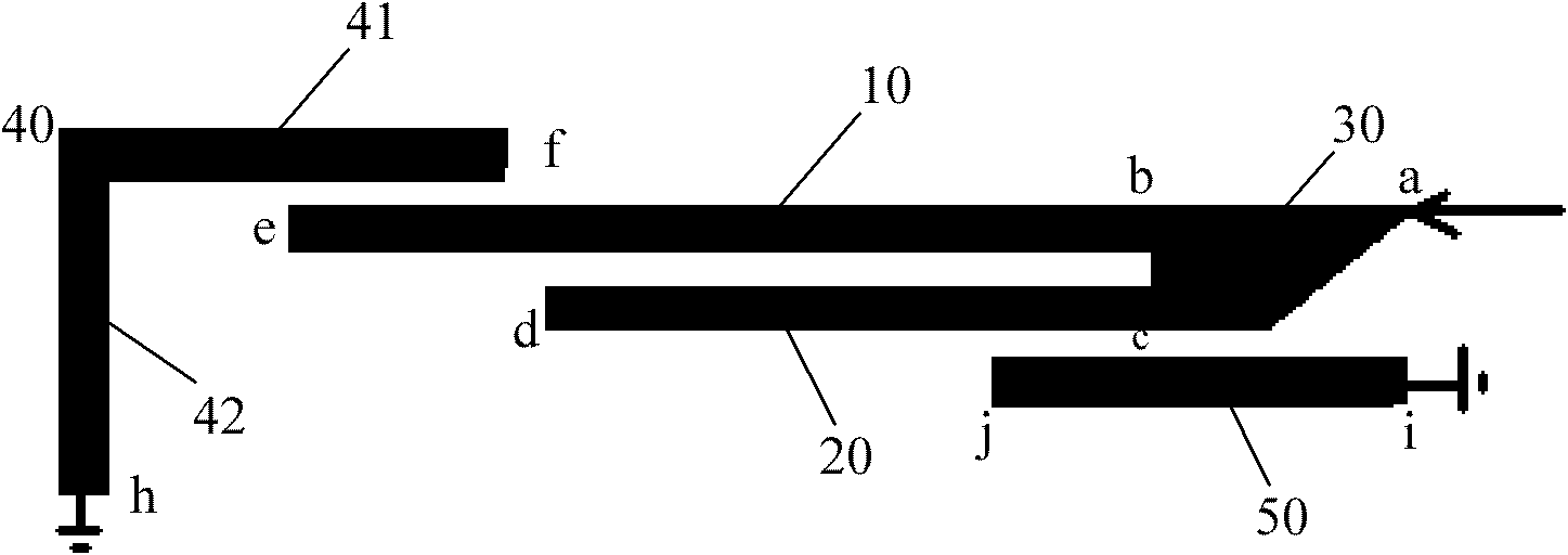
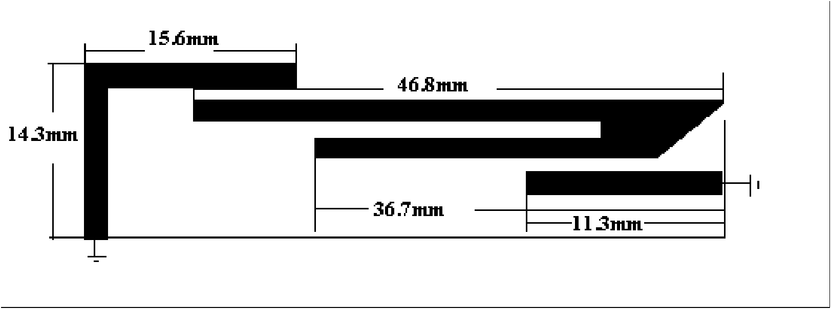
[0028] An embodiment of the present invention provides a printed antenna, such as figure 1 As shown, the antenna area needs clearance, and the antenna is printed on the PCB board. The printed antenna in this embodiment includes: a signal feeding branch and a grounding branch. The signal feeding branch includes: a first feeding sub-branch 10, a second feeding sub-branch 20, and a connecting block 30 including a feeding point. The branches...


PUM


Abstract

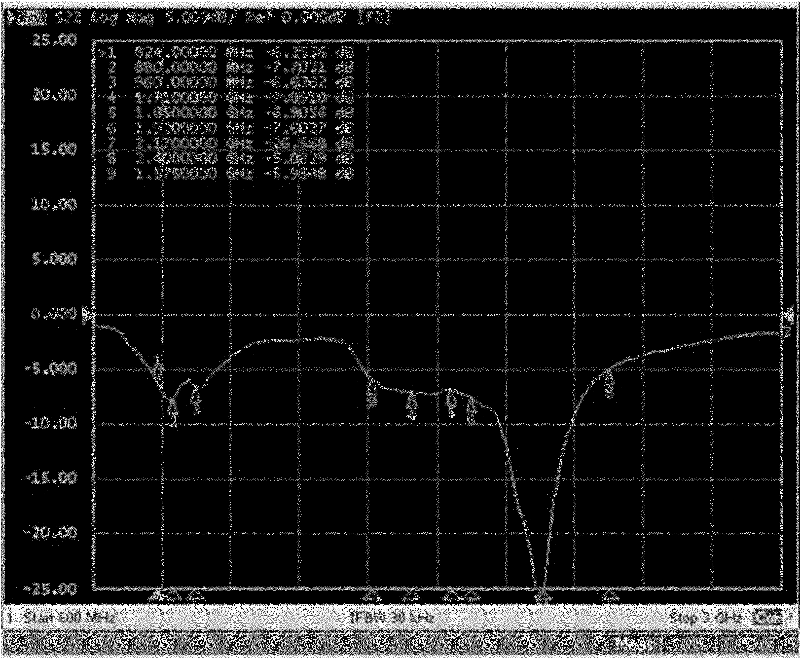
The embodiment of the invention provides a printed antenna comprising a signal feeding branch and a grounding branch, wherein the signal feeding branch comprises a first feeding sub-branch, a second feeding sub-branch and a connecting block comprising feeding points; the grounding branch comprises a first grounding sub-branch and a second grounding sub-branch; and the signal feeding branch is coupled with the grounding branch. The printed antenna provided by the embodiment of the invention has an ultra wide band, has a working frequency covering the range of 700-2600MHz, gives consideration to LTE (Long Term Evolution) and GPS (Global Position System) channels, is simple in realization form, and is very convenient to apply.

Description

Technical field [0001] The invention relates to the technical field of antenna design, in particular to a printed antenna. Background technique [0002] An antenna is a conductor extending from the transmitter or receiver that can resonate with the signal. The lower the frequency, the longer the antenna. The higher the frequency, the opposite is true. Nowadays, radio equipment such as mobile phones and wireless routers have very high frequencies and antennas can be used. The antenna is very small, so the antenna can be etched on the circuit board of the machine (that is, a small piece of copper), or printed on a flexible substrate with a printed material containing conductive materials, collectively called a printed antenna. [0003] The development trend of terminal gateway products (FMC) is becoming thinner and thinner, and correspondingly, the available height of the built-in antenna is also continuously reduced. [0004] At present, an industry standard development trend is a sm...

Claims


Application Information

Patent Timeline
Patent Type & Authority Patents(China)
IPC IPC(8): H01Q9/04H01Q5/00H01Q1/48H01Q5/50
Inventor 王克猛陈鹏于亚芳
Owner HUAWEI DEVICE CO LTD
Learn More