A dual-band vortex electromagnetic wave array antenna

A technology of vortex electromagnetic waves and array antennas, which is applied in the directions of antenna arrays, antennas, antenna arrays, etc. that are energized separately, can solve the problems that array antennas cannot radiate vortex electromagnetic waves, etc., and achieve the effect of compact structure and reasonable design

Active Publication Date: 2020-11-10
SHANXI UNIV
View PDF9 Cites 0 Cited by
  • Summary
  • Abstract
  • Description
  • Claims
  • Application Information

AI Technical Summary

Problems solved by technology

[0004] In order to solve the technical problem that the existing array antenna cannot radiate vortex electromagnetic waves on dual frequency bands, the present invention provides a dual frequency band vortex electromagnetic wave array antenna

Method used


Image

  • A dual-band vortex electromagnetic wave array antenna
  • A dual-band vortex electromagnetic wave array antenna
  • A dual-band vortex electromagnetic wave array antenna

Examples


Embodiment Construction

[0020] The technical solutions of the present invention will be clearly and completely described below in conjunction with the accompanying drawings and embodiments.

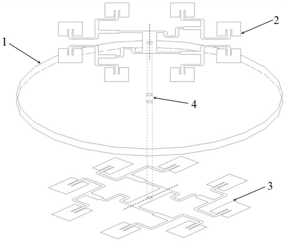
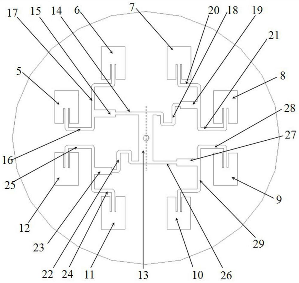
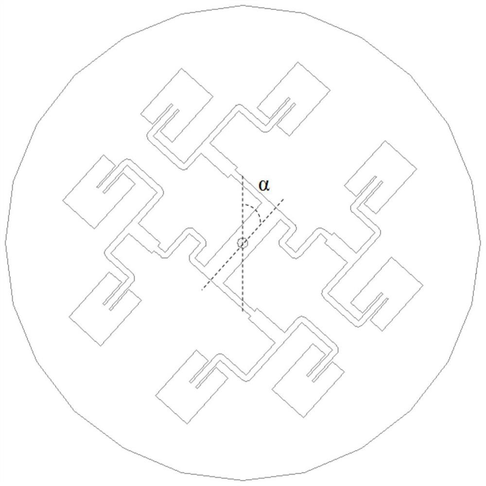
[0021] Such as Figure 1 to Figure 3 As shown, a dual-band vortex electromagnetic wave array antenna, wherein: the dual-band vortex electromagnetic wave array antenna includes: a dielectric substrate 1, an upper layer antenna array 2 and a lower layer antenna array 3, and the upper layer antenna array 2 and the lower layer antenna array 3 have the same structure, the upper antenna array 2 and the lower antenna array 3 are mounted on the upper surface and the lower surface of the dielectric substrate 1 respectively and the angle between the center line of the upper antenna array 2 and the center line of the lower antenna array 3 is α is 42°; a coaxial feeding probe 4 is arranged between the center of the upper antenna array 2 and the center of the lower antenna array 3;

[0022] The upper layer antenna array 2 i...


PUM


Abstract

The invention belongs to the technical field of antennas and in particular to a dual-band vortex electromagnetic wave array antenna, and mainly solves a technical problem that a conventional array antenna cannot radiate vortex electromagnetic waves on dual bands. The dual-band vortex electromagnetic wave array antenna includes a dielectric substrate, an upper antenna array, and a lower antenna array. The upper antenna array and the lower antenna array have the same structure and are mounted on the upper surface of the dielectric substrate respectively. An intersection angle [alpha] between thecenter line of the upper antenna array and the center line of the lower antenna array is 42 degrees. The dual-band vortex electromagnetic wave array antenna is reasonable in design and compact in structure, solves the technical problem that the conventional array antenna cannot radiate vortex electromagnetic waves on dual bands, and is suitable for wireless communication.

Description

technical field [0001] The invention belongs to the technical field of antennas, and in particular relates to a dual-band vortex electromagnetic wave array antenna. Background technique [0002] The angular momentum of electromagnetic waves includes spin angular momentum and orbital angular momentum. Electromagnetic waves carrying orbital angular momentum are different from ordinary plane waves. The center intensity of the beam is zero, and the phase wave front presents a spiral characteristic, also known as vortex electromagnetic waves. The vortex electromagnetic wave uses the mode number m to represent the rotation degree of its phase wave front. Theoretically, there are infinitely many modal numbers m of the vortex electromagnetic wave, and there is orthogonality between different modes. Using this vortex electromagnetic wave This feature can greatly improve the spectrum utilization and communication capacity of the communication system. [0003] Orbital angular momentu...

Claims


Application Information

Patent Timeline
Patent Type & Authority Patents(China)
IPC IPC(8): H01Q5/50H01Q21/00H01Q21/06
CPCH01Q5/50H01Q21/0006H01Q21/065
Inventor 张文梅窦海鹏陈新伟韩丽萍杨荣草刘宇峰
Owner SHANXI UNIV
Why Eureka
Try Eureka