
Method for manufacturing SOI wafer, and SOI wafer

A manufacturing method and chip technology, applied in semiconductor/solid-state device manufacturing, electrical components, electrical solid-state devices, etc., can solve problems such as the inability to form a deep position of the chip, the difficulty of the thickness of the surface component area, and the inability of the BOX layer to become a dense structure.

Active Publication Date: 2011-07-06
SHIN-ETSU HANDOTAI CO LTD
View PDF2 Cites 1 Cited by
  • Summary
  • Abstract
  • Description
  • Claims
  • Application Information

AI Technical Summary

Problems solved by technology

Although the SIMOX method is simple, it is difficult to increase the thickness of the surface component area because the BOX layer formed by the oxygen ion implantation layer is limited to the extreme surface layer and cannot be formed at a deeper position in the chip.
In addition, the formed BOX layer cannot have a dense structure, and when an SOI chip is used as a chip for component manufacturing, there is a disadvantage that it is difficult to obtain a complete insulation withstand voltage which is the greatest advantage.
[0005] In addition, the film thickness of the SOI layer of the SOI chip is a thick film of several micrometers to tens of micrometers. This kind of SOI chip is a very useful chip as a bicarrier module or a power module, but it is known that it is necessary to manufacture low-cost and high-quality SOI chips are difficult even if they use the above-mentioned bonding method and SMARTCUT method by grinding and grinding.
The reason is: in the case of the bonding method implemented by grinding and grinding, it is necessary to first bond the oxide-coated silicon chip and the bare chip and perform a bonding heat treatment above 1100 ° C, and then perform grinding and grinding treatment. It is very difficult to manufacture the SOI layer with the required thickness of the SOI layer. The process is complicated and it is very difficult to make the thickness of the SOI layer uniform. On the other hand, in the case of the SMARTCUT method, the thickness of the SOI layer depends on the ion implantable Depth (that is, the accelerating voltage of the ion implantation device), in the case of the usual implantation device, the maximum accelerating voltage is about 200keV, and only an SOI layer with a thickness of about 2 microns can be obtained at most

Method used


Image

  • Method for manufacturing SOI wafer, and SOI wafer
  • Method for manufacturing SOI wafer, and SOI wafer
  • Method for manufacturing SOI wafer, and SOI wafer

Examples


experiment example

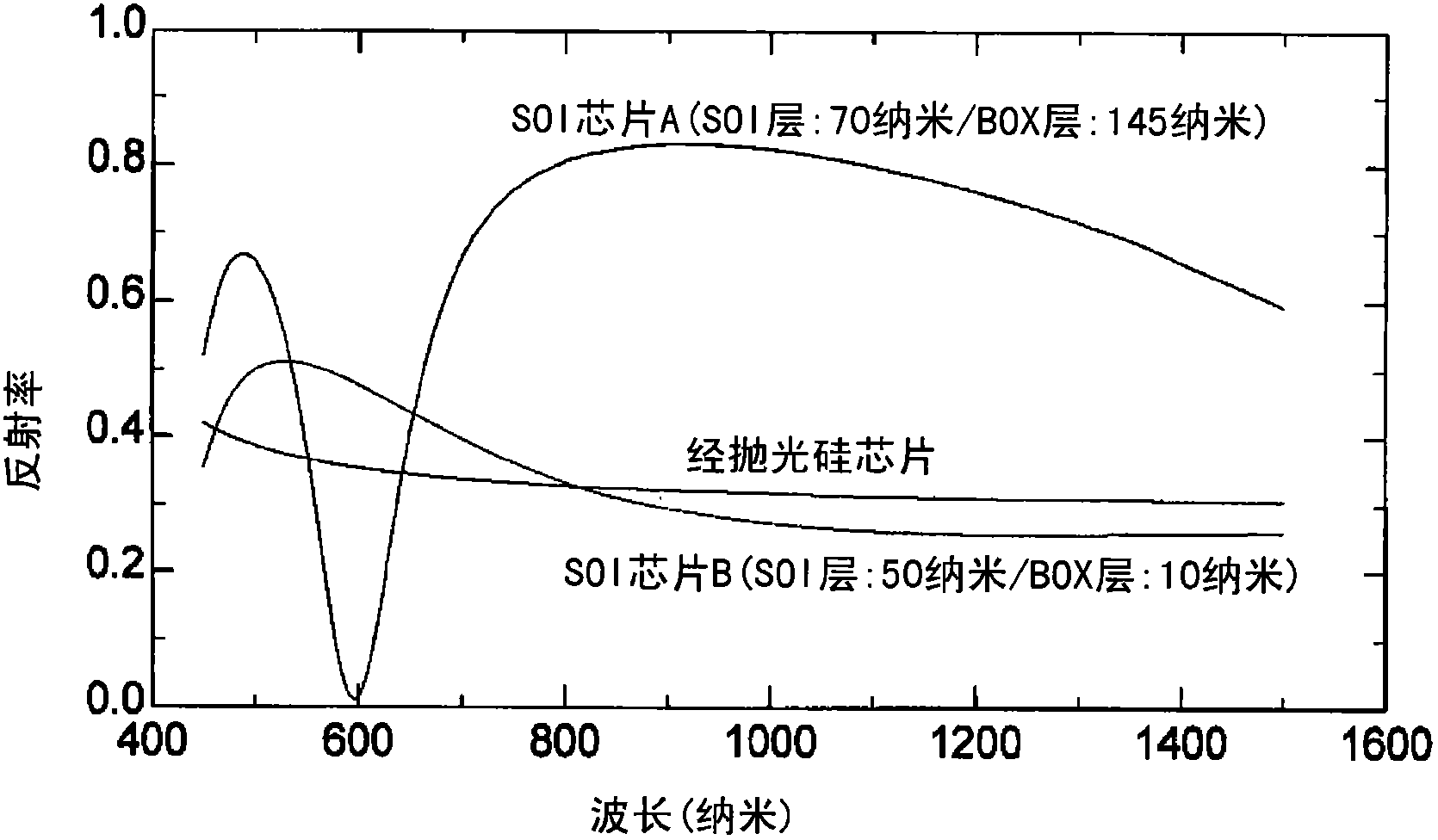
[0044] To confirm the simulation results, polished silicon chips, SOI chip A (SOI layer: 70 nm, BOX layer: 145 nm), SOI chip B (SOI layer: 50 nm, BOX layer: 10 nm) each having a diameter of 300 mm were used. ), and hydrogen (H 2 ) annealing (under an environment of 100% hydrogen gas) was performed at 1100° C. for 900 seconds using a monolithic lamp heating type epitaxial growth apparatus (Centura: manufactured by APPLIED MATERIALS). The occurrence of slip was evaluated based on a slip emphasis display image of a chip stress measurement device SIRD (Scanning Infra Red Depolarization; Scanning Infra Red Depolarization).

[0045] First, for a polished silicon chip, conditions for lamp heating power balance (chip top and bottom, chip inside and outside) conditions to achieve no slip after hydrogen annealing were obtained. The results of hydrogen annealing SOI chips A and B under this condition, as shown in Figure 7 shown. The SOI chip B, which had approximately the same reflect...


PUM


Abstract

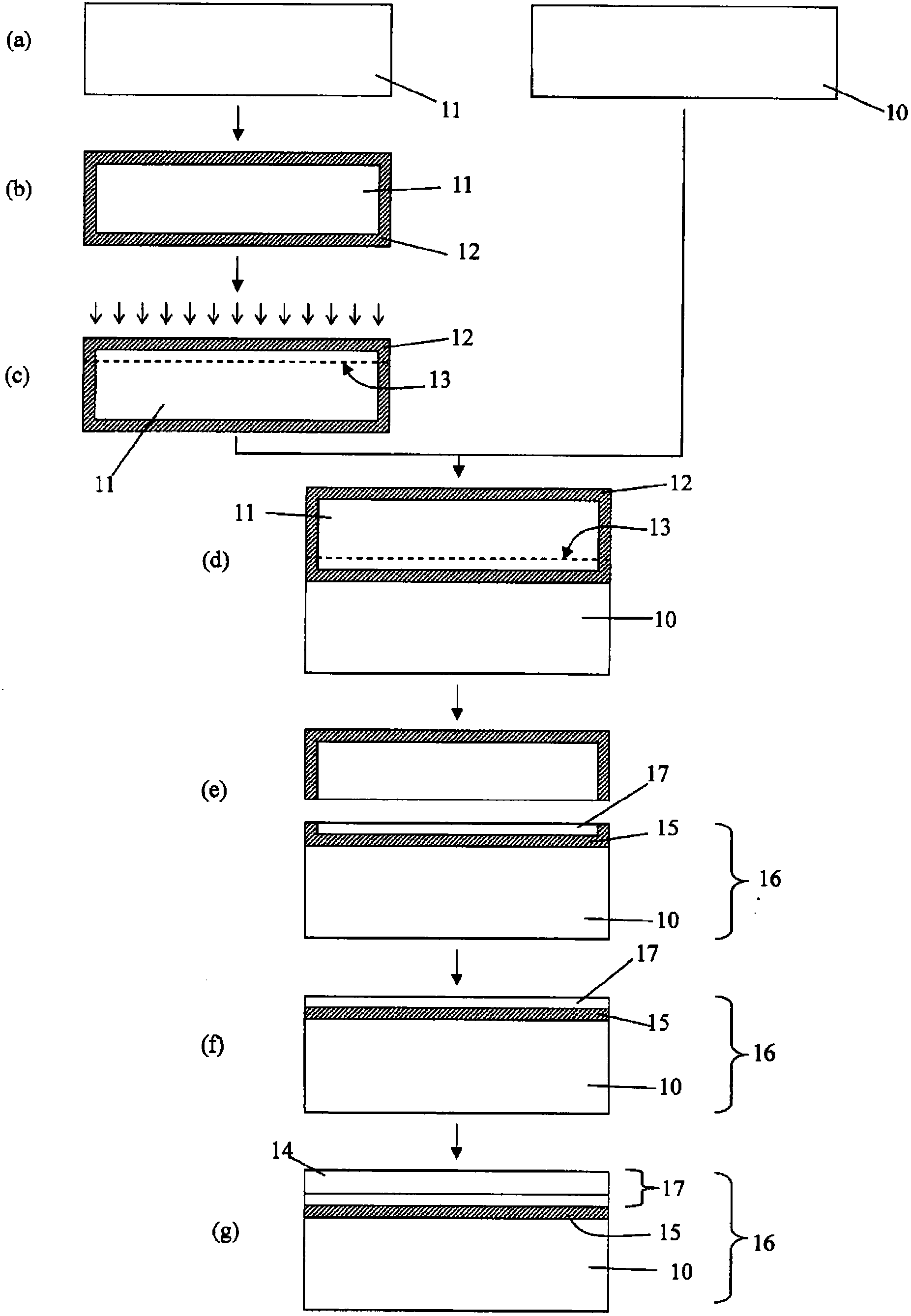
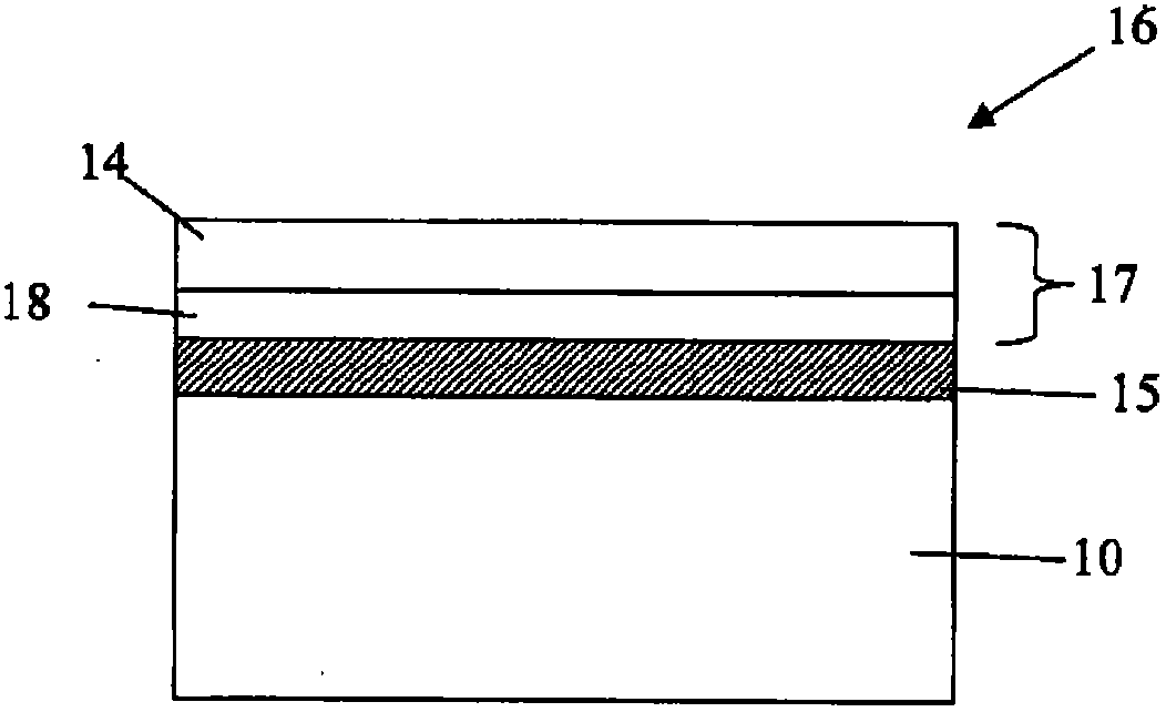
Disclosed is a method for manufacturing an SOI wafer, comprising providing an SOI wafer comprising an SOI layer provided on a BOX layer and growing an epitaxial layer on the SOI layer to increase the thickness of the SOI layer. In the method, the SOI wafer for epitaxial layer growth has an infrared reflectance of not less than 20% and not more than 40% in an infrared wavelength range of 800 to 1300 nm. The method can provide a high-quality SOI wafer, which comprises an SOI layer having a thickness increased by growing an epitaxial layer and has no significant slip dislocation or the like, at low cost with high productivity.

Description

technical field [0001] The present invention relates to an SOI chip (silicon chip on insulating layer) and its manufacturing method. The SOI chip is formed by growing a silicon epitaxial layer on the SOI layer of the SOI chip as a substrate to thicken the SOI layer. Background technique [0002] As a method of manufacturing an SOI chip, a die-bonding method and a SIMOX (Separation by Implantation of oxygen) method are generally known. Chip bonding method, for example, two silicon chips are bonded through an oxide film without using an adhesive, and after heat treatment (1000-1200 ° C) to improve the bonding strength, one of the chip films is bonded by grinding, grinding or etching. The advantage of this method is that the crystallinity of the SOI layer or the reliability of the buried oxide film (BOX layer) is equal to that of a common silicon chip. In addition, the disadvantage is that the uniformity of the film thickness of the SOI layer has its limit (at most ±0.3 micron...

Claims


Application Information

Patent Timeline
Patent Type & Authority Applications(China)
IPC IPC(8): H01L21/02H01L21/205H01L27/12
CPCH01L21/02532H01L21/0262H01L21/76254H01L21/02381H01L21/20H01L27/12
Inventor 冈哲史桑原登
Owner SHIN-ETSU HANDOTAI CO LTD
Learn More