Backlight module and assembly method thereof

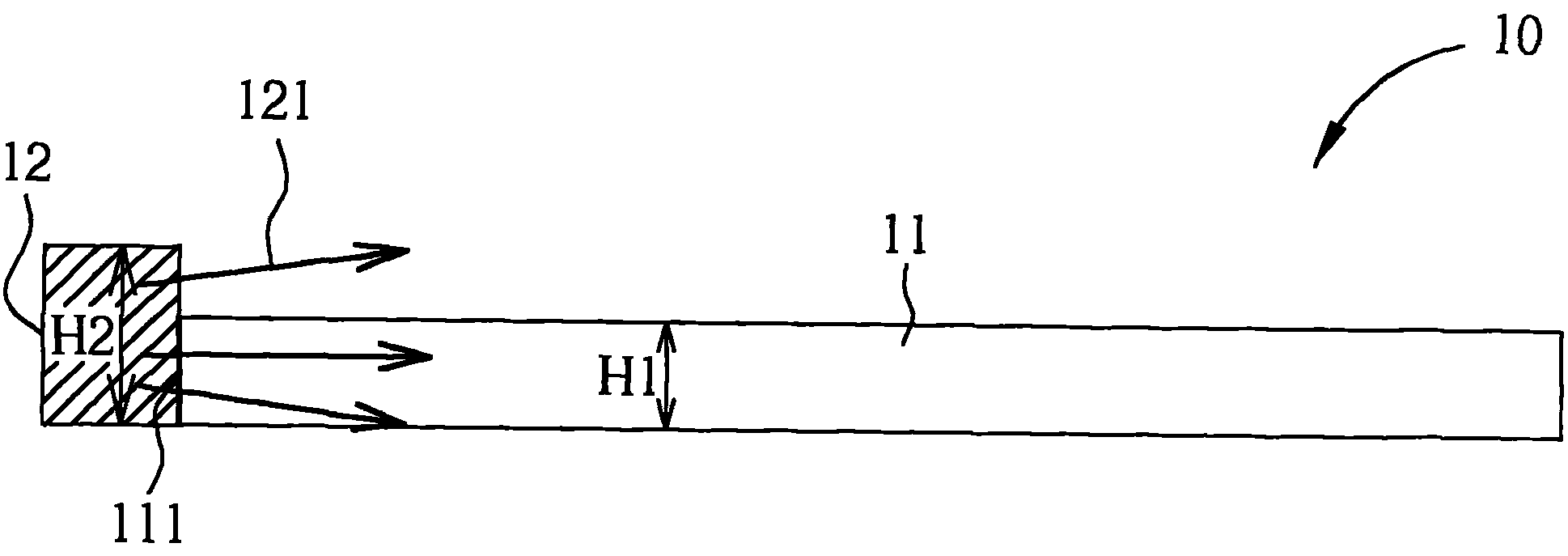
The technology of a backlight module and an assembly method, which is applied in the field of backlight modules and its assembly, can solve problems such as the inability to cover light-emitting diode components 12, light loss, and reduce light utilization, so as to achieve the effect of improving light utilization

Inactive Publication Date: 2011-07-13
AU OPTRONICS CORP
View PDF3 Cites 16 Cited by
  • Summary
  • Abstract
  • Description
  • Claims
  • Application Information

AI Technical Summary

Problems solved by technology

Due to the difference in thickness between the two, the light emitting diode assembly 12 cannot be completely covered by the light incident surface 111 of the light guide plate 11
Therefore, part of the light 121 emitted by the LED assembly 12 that is not covered by the light incident surface 111 of the light guide plate 11 cannot directly enter the light incident surface 111 of the light guide plate 11, resulting in loss of light, thereby reducing the utilization rate of light.

Method used


Image

  • Backlight module and assembly method thereof
  • Backlight module and assembly method thereof
  • Backlight module and assembly method thereof

Examples


Embodiment Construction

[0037] Below in conjunction with accompanying drawing, structural principle and working principle of the present invention are specifically described:

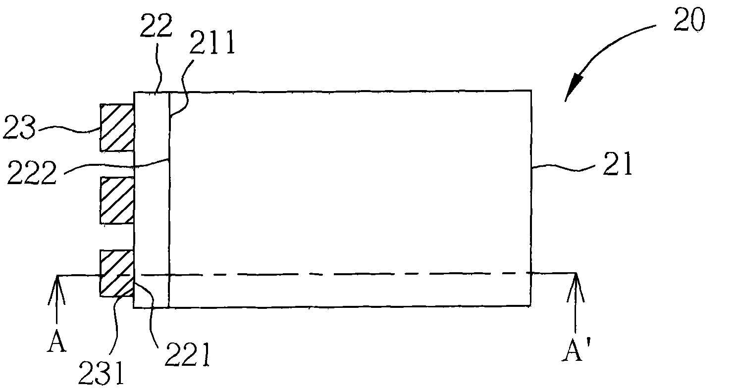
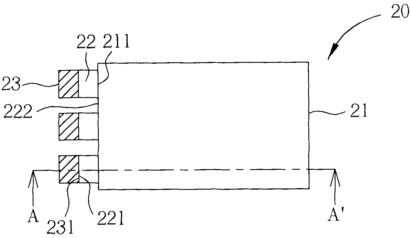
[0038] Please refer to Figure 2A , Figure 2B and image 3 . Figure 2A It is a schematic top view of a backlight module in a first preferred embodiment of the present invention, Figure 2B It is a schematic top view of a variant embodiment of the backlight module of a second preferred embodiment of the present invention, image 3 along Figure 2A and Figure 2B The cross-sectional schematic diagram of the backlight module of the cross-section line A-A', wherein due to the different angles of drawing, some components are not shown in the part of the figure. Such as Figure 2A , Figure 2B and image 3 As shown, the backlight module 20 of this embodiment includes a light guide plate 21, at least one light guide block 22, a plurality of light emitting components 23, and a reflector 24 (for convenience of description, ...


PUM


Abstract

The invention provides a backlight module and an assembly method thereof, comprising a substrate, a light guide plate, a light guide block and a light-emitting assembly. The light guide plate is provided with a first light-inlet surface provided with a first thickness. The light guide block is provided with a second light-inlet surface and a second light-outlet surface oppositely disposed, the second light-outlet surface is provided with a second thickness, and the second light-inlet is provided with a third thickness, the second thickness of the second light-outlet surface is smaller than orequal to the first thickness of the first light-inlet surface, and the second light-outlet surface is covered by the first light inlet surface. The light-emitting assembly and the second light-inlet surface of the light guide block are oppositely disposed, wherein the light-emitting assembly is provided with a fourth thickness, the fourth thickness of the light-emitting assembly is smaller than or equal to the third thickness of the second light-inlet surface, and a light-emitting surface of the light-emitting assembly is covered by the second light-inlet surface.

Description

technical field [0001] The invention relates to a backlight module and an assembly method thereof, in particular to a backlight module with a light guide block capable of improving light utilization and an assembly method thereof. Background technique [0002] Recently, with the development of liquid crystal display panels, the design trends of various electronic products using liquid crystal display panels such as mobile phones (Mobile Phone), personal digital assistants (PDA) and notebook computers (Notebook) are all towards light, thin and short. , Small development. Among them, thinner electronic products are more popular with consumers, so the backlight modules used to provide backlight gradually use smaller light-emitting diodes (LEDs) to replace traditional relatively larger cold-cathode fluorescent lamps (CCFL) as The light source generator is used to reduce the volume of the backlight module. Therefore, the light guide plate used in the backlight module structure ...

Claims


Application Information

Patent Timeline
Patent Type & Authority Applications(China)
IPC IPC(8): F21S8/00F21V8/00F21V17/10F21V19/00
Inventor 陈志光
Owner AU OPTRONICS CORP
Why Eureka
Try Eureka