Spiral cutter for composite positioned cutting

A compound positioning and cutting tool technology, which is applied to twist drills and other directions, can solve the problems of reduced hardness of the cutter head, poor centering structure, and wear of the cutter head.

Inactive Publication Date: 2011-07-20
李仕清
View PDF7 Cites 15 Cited by
  • Summary
  • Abstract
  • Description
  • Claims
  • Application Information

AI Technical Summary

Problems solved by technology

[0002] At present, the twist drills used in mechanical processing are composed of chisel edge, cutting edge, helical secondary edge, and side edge. The cutting edge and secondary edge generally have a single structure, and the centering structure is poor. A large amount of heat is easily generated when (milling) a workpiece with higher hardness, which causes the hardness of the cutter head to decrease, causing the wear of the cutter head. It is symmetrical when working, and the cutting amount is generally only tens of microns to 1 mm, so it is difficult to grasp the angle and height during manual grinding. In addition, the precision of these twist drills and the processed holes is unqualified, which is easy to Waste products occur, and at the same time, there is a problem of lifting the workpiece when processing thin workpieces, causing industrial accidents

Method used


Image

  • Spiral cutter for composite positioned cutting
  • Spiral cutter for composite positioned cutting
  • Spiral cutter for composite positioned cutting

Examples


Embodiment approach 1

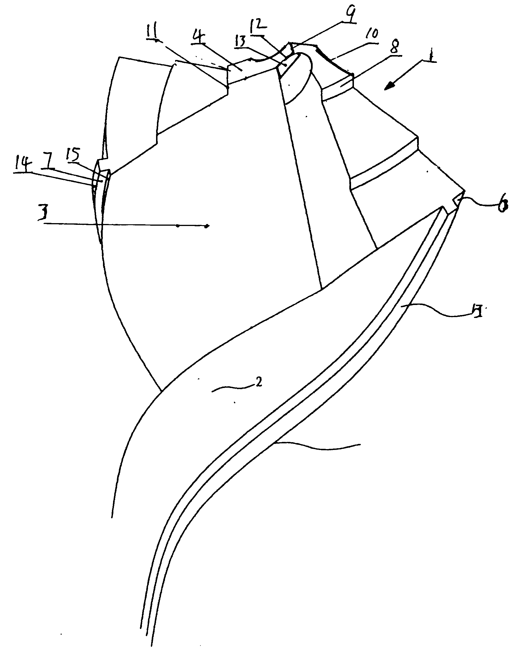
[0034] Such as figure 1 As shown, the spiral tool for composite positioning cutting according to the first embodiment of the present invention includes a tool head 1. The tool head 1 is integrally provided with two spiral strips 2, and the surface of the spiral strip 2 facing the cutting direction is the cutting surface 3. The top and back side of the cutting surface 3 is the rear cutting surface 4, and the outermost surface of the spiral strip 2 is the secondary cutting surface 5. The cutting surface 3 and the secondary cutting surface 5 intersect to form a secondary cutting edge 14, and the inner side of the cutting surface 3 is axially The center begins to form one or more steps 6 in a manner that gradually decreases in height to the outside. The outermost one is the reinforcement platform 7, and the convex cutting surface 3 intersects with a composite secondary edge 15 formed on the rear cutting surface 4. From the chisel edge 9 to both outer sides, a stepped portion 8 is fo...

Embodiment approach 2

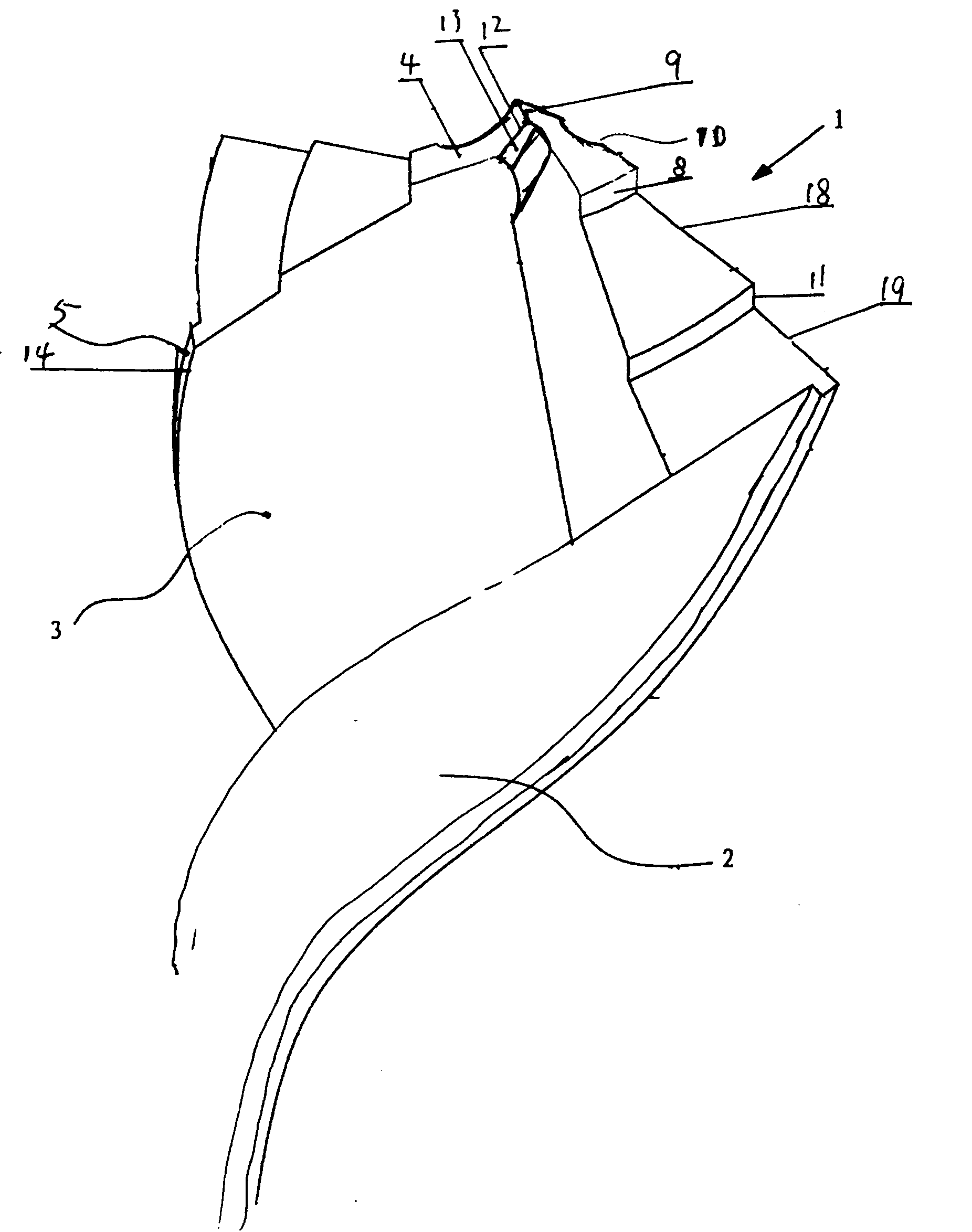
[0037] Such as figure 2 As shown, the spiral tool for composite positioning cutting according to the second embodiment of the present invention includes a tool head 1. The tool head 1 is integrally provided with two spiral strips 2, and the surface of the spiral strip 2 facing the cutting direction is the cutting surface 3. The top and back side of the cutting surface 3 is the rear cutting surface 4, and the outermost surface of the spiral 2 is the secondary cutting surface 5. The cutting surface 3 and the secondary cutting surface 5 intersect to form a secondary cutting edge 14, and the chisel edge of the rear cutting surface 4 At 8 places, one or more steps 8 are formed in such a way that the height gradually decreases toward the outside. The convex rear cutting surface 4 and the cutting surface 3 intersect the cutting surface 3 to form at least one level of composite cutting edge 18 or 19, the cutting edge 10 A stepped edge 11 is formed on the stepped cutting surface. A cham...

Embodiment approach 3

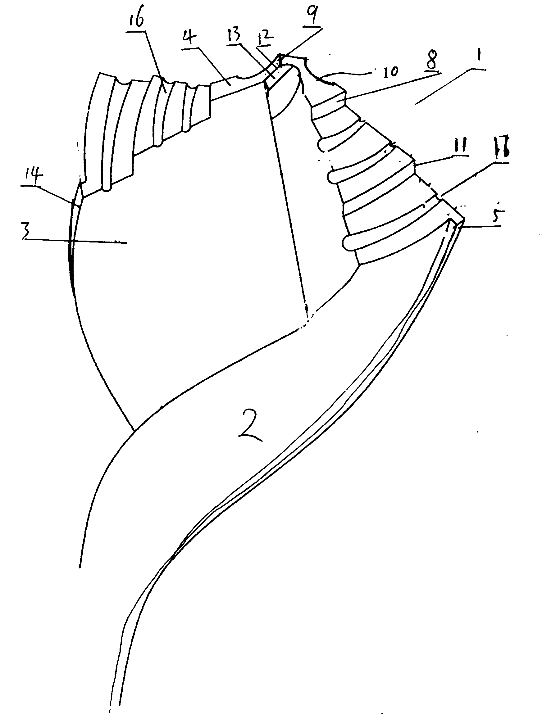
[0040] Such as image 3 As shown, the spiral tool for composite positioning cutting according to the third embodiment of the present invention includes a tool head 1. The tool head 1 is integrally provided with two spiral strips 2, and the surface of the spiral strip 2 facing the cutting direction is the cutting surface 3. The top and back side of the cutting surface 3 is the rear cutting surface 4, and the outermost surface of the spiral 2 is the secondary cutting surface 5. The cutting surface 3 and the secondary cutting surface 5 intersect to form a secondary cutting edge 14, and the inner tip of the rear cutting surface 4 The chisel edge 9 begins to form one or more steps 6 in a manner of gradually decreasing its height to the outside. At least one stepped edge 11 is formed at the intersection of the stepped rear cutting surface 4 and the cutting surface 3, and on the stepped cutting edge 10 At least one notch edge 17 is provided with grooves 16 with an opening extending tow...


PUM


Abstract

The invention provides a spiral cutter for composite positioned cutting. The cutter has high stability, high radiating efficiency, and long service life and is easy to position in drilling processing. The cutter comprises a cutter head, and is characterized in that: at least stepped cutting edges, chamfering edges and chisel edges on two side of the spiral cutter 1 form S-shaped cutting edges 2; the stepped cutting edges or the chamfering edges are provided with at least one notch edge 3, and step parts of which the height is gradually reduced are formed towards two outer sides from the chisel edges on a rear cutting face; stepped edges 4 are formed on the stepped cutting faces of the cutting edges, and step parts of which the height is gradually reduced are formed towards two outer sides of the chisel edges on the rear cutting face; stepped edges are formed on the stepped rear cutting faces of the cutting edges; and at least one step of stepped edge is provided with at least one notch edge, and a groove distributed in an enlargement mode extends from the opening of the notch edge to the rear cutting face or the cutting faces.

Description

Technical field: [0001] The invention relates to a spiral cutter for compound positioning and cutting. The spiral cutter for compound positioning and cutting is used in drilling machine processing and fitter maintenance. Background technique: [0002] At present, the twist drills used in machining are composed of chisel edge, cutting edge, spiral secondary edge, and side edge. The cutting edge and secondary edge are roughly of a single structure with poor centering structure. These twist drills are extremely not durable, especially when drilling (Milling) When cutting workpieces with higher hardness, it is easy to generate a lot of heat, which leads to the reduction of the hardness of the cutter head and the wear of the cutter head. At the same time, the cutter head also has the defect of easy breakage. Moreover, because the cutting edges on both sides of the cutter head are in The work is symmetrical, and the cutting amount is generally only tens of microns to 1 mm, so it is dif...

Claims


Application Information

Patent Timeline
Patent Type & Authority Applications(China)
IPC IPC(8): B23B51/02
Inventor 李仕清
Owner 李仕清
Why Eureka
Try Eureka