
Chisel holder system

Inactive Publication Date: 2010-08-31
WIRTGEN GMBH
View PDF7 Cites 38 Cited by
  • Summary
  • Abstract
  • Description
  • Claims
  • Application Information

AI Technical Summary

Benefits of technology

[0006]It is one object of this invention to provide a chisel holder system of the type mentioned but with a long service life.
[0011]If the contact face of the chisel holder projects past or beyond the support surface of the base element in the area of the depression and terminates there, the contact face of the chisel holder always projects past the support surface in the area of the depression. In this way a formation of a seam on the base element is dependably prevented in a simple manner.
[0012]In a further development of this step, the contact face of the chisel holder projects past the support surface of the base element on all sides. Thus, the contour of the contact face of the base element is shifted inward with respect to the contact face of the chisel holder. If wear should occur, the support surface will work itself into the support surface of the chisel holder and it itself remains unchanged. This embodiment also protects the support surface from removed material flowing off the chisel. In this way wash-outs on the support surface are prevented in a simple manner.
[0013]In one embodiment of this invention, the support surface of the base element is formed by a shoulder, whose cross-sectional dimensions extending parallel with the support surface are less than or equal to the contact face, at least in the area adjoining the support surface, so that on an outside the contact face projects past the shoulder in this area. In this way, the shoulder forms a wear area, inside of which the support surface can be worn off, but can always support the chisel holder to assure its correct function. It is thus possible to maintain the service life of the base element for a long time.

Problems solved by technology

In contrast, the base element must be protected as much as possible from the effects of wear, because it is the expensive part of the chisel holder system, which can only be replaced with a large mounting effort.

Method used


Image

  • Chisel holder system
  • Chisel holder system
  • Chisel holder system

Examples


Embodiment Construction

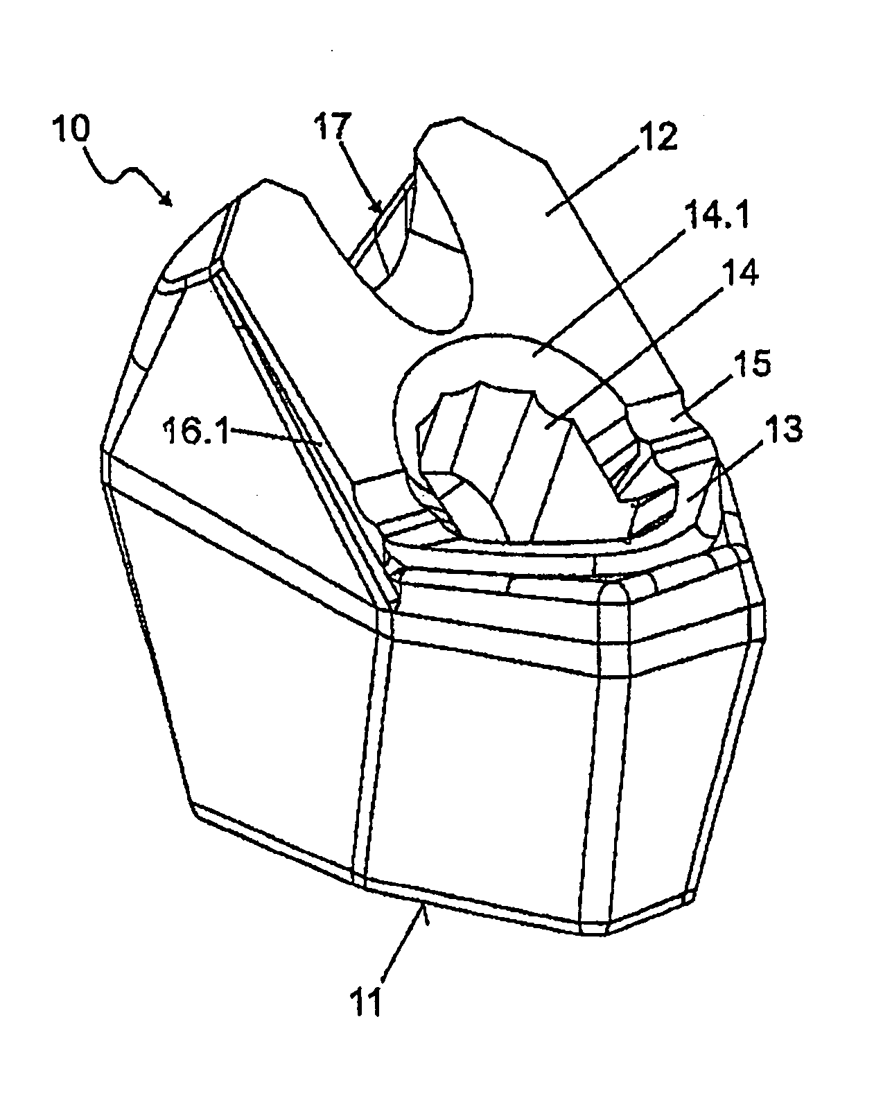
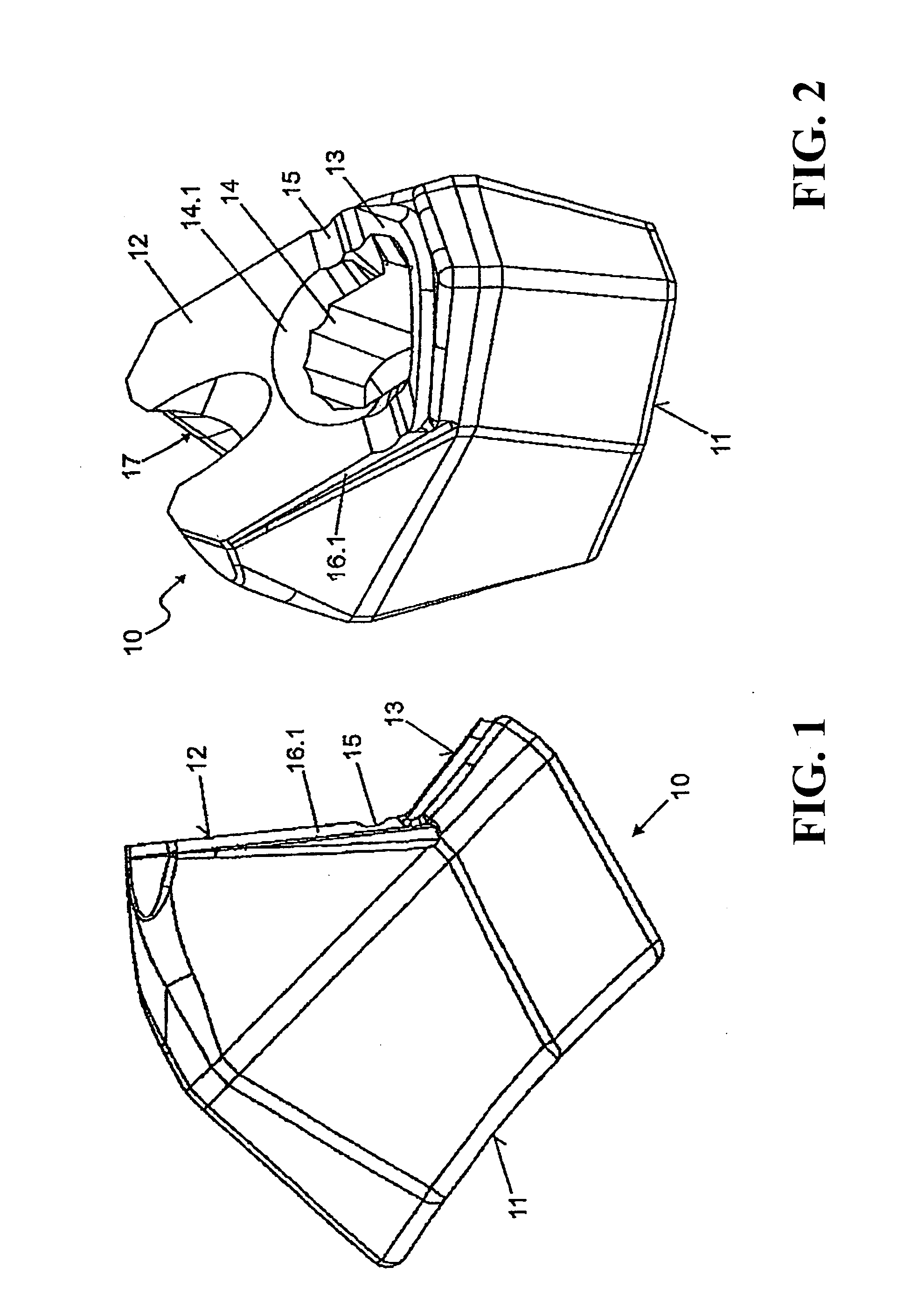
[0024]FIGS. 1 and 2 show a base element 10, which can be fastened by a curved connection face 11 to the exterior of a milling roller pipe of, for example a road milling machine. The base element 10 has a support surface 12, to which a shoulder 13 is connected at an angle. A plug-in receptacle 14 is cut in the form of a recess into the base element 10 in the transition area between the shoulder 13 and the support surface 10. The plug-in receptacle makes a transition by a cross-sectional widening 14.1 into the support surface 12, or into the shoulder 13.

[0025]The support surface 12 is supported by a shoulder 16.1. In this case, the shoulder 16.1 has the same cross-sectional dimension vertically in a direction with respect to the support surface 12 as the support surface 12. In the transition area between the support surface 12 and the shoulder 13, the support surface 12 is closed off by a depression 15. The depression 15 is arranged in the form of a groove on both sides of the plug-in...


PUM


Abstract

A chisel holder system including a base part and a chisel holder. The base part includes a socket wherein the chisel holder with a plug-in insert is introduced. The chisel holder has a bearing surface supported on a supporting surface of the base plate, and the base part has a shoulder connected to the supporting surface. A replacement chamber is formed between the shoulder and a facing end surface of the chisel holder. According to this invention, the supporting surface is placed in the transition region in relation to the shoulder by at least one recess of the shoulder so that the flat-shaped connection between the supporting surface and the shoulder, in the region of the recess, is interrupted in order to optimize the resistance to wear and tear of the base part.

Description

BACKGROUND OF THE INVENTION[0001]1. Field of the Invention[0002]This invention relates to a chisel holder system with a base element and a chisel holder, wherein the base element has a plug-in receptacle into which the chisel holder is inserted with a plug-in neck, the chisel holder is supported by a contact face on a support surface of the base element, the base element has a shoulder adjoining the support surface and a seating-adjustment space is formed between the shoulder and a facing end face of the chisel holder.[0003]2. Discussion of Related Art[0004]A chisel holder system is known from German Patent Reference DE 43 22 401 A1. This chisel holder system has a base element which can be welded, for example, to the shell face of a milling roller pipe of a road milling machine, and a plug-in receiver, into which a shaft-like plug-in neck of a chisel holder can be inserted. The base element has a shoulder around the plug-in receiver. The chisel holder is spaced apart from the shoul...

Claims


Application Information

Patent Timeline
Patent Type & Authority Patents(United States)
IPC IPC(8): E21C35/18
CPCE21C35/18E21B10/00
Inventor HOLL, BERNDSIMONS, DIETER
Owner WIRTGEN GMBH
Learn More