Laser cleaving method and apparatus for optical fiber cables

a laser cleaving and optical fiber cable technology, applied in the direction of optical elements, manufacturing tools, instruments, etc., can solve the problem of adding an additional expense to the laser cleaving apparatus, and achieve the effect of optimal results

Active Publication Date: 2006-07-25
FURAKAWA ELECTRIC NORTH AMERICA INC
View PDF8 Cites 44 Cited by
  • Summary
  • Abstract
  • Description
  • Claims
  • Application Information

AI Technical Summary

Benefits of technology

[0007]In one embodiment of the cleaving apparatus, the desired distortion of the intensity profile of the beam to other than normal Gaussian is achieved by the centerline of the beam passing through the focusing lens being offset from the centerline of the lens. The beam emerging from the lens has the desired chisel shape, i.e., one substantially straight side and one angled side as a result of a non-symmetrical intensity distribution. The cleaving apparatus includes an arrangement, such as a microscopic camera, CPU, and driven positioning means for monitoring the cleaving process and for positioning the elements involved, i.e., the ferrule end face with the fiber mounted therein and the lens, to achieve optimum results.

Problems solved by technology

It is possible to use, instead, an aspheric lens or a filtering apparatus, which, while efficacious, add an additional element of expense to the cleaving apparatus.

Method used


Image

  • Laser cleaving method and apparatus for optical fiber cables
  • Laser cleaving method and apparatus for optical fiber cables
  • Laser cleaving method and apparatus for optical fiber cables

Examples


Embodiment Construction

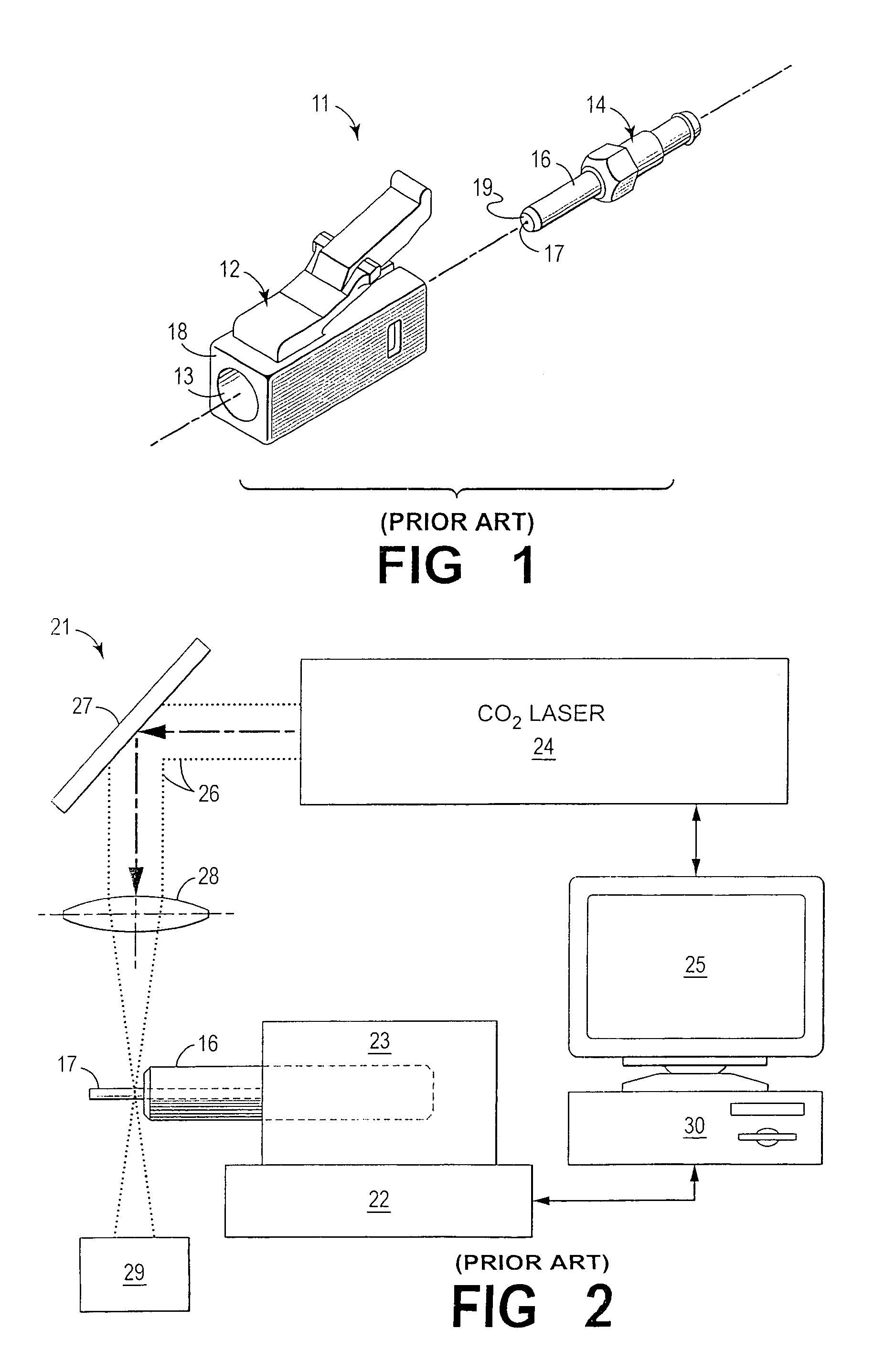
[0019]FIG. 1 is an exploded perspective view of a portion of a connector 11 which comprises a front housing 12 having a bore 13 extending therethrough into which a barrel member 14 is inserted. Member 14 has a ferrule 16 affixed thereto which contains the optical fiber 17, which is generally cemented within the ferrule. When assembled, the ferrule 16 projects out of the front portion 18 of the housing with its front face so positioned to butt against a connecting ferrule. The connector 11 is shown by way of example and is not intended to be representative of any particular connector type being intended, instead to represent any connector having a ferrule within.

[0020]As discussed hereinbefore, it is desirable that the front end of fiber 17 is flush with the front face 19 of the ferrule, and that it be flat, in a plane orthogonal to the connector centerline. The front face 19 of ferrule 16 is shown in FIG. 1 as being curved, which is common practice in the prior art, but it is necess...


PUM

PropertyMeasurementUnit
mode field diameter MFRaaaaaaaaaa
wavelengthaaaaaaaaaa
timeaaaaaaaaaa

Abstract

A laser cleaving apparatus for use in terminating optical fiber cable ends has a laser beam source, the output of which is directed through a beam distorting member, which produces a beam having a chisel shape with a substantially flat side normal to the axis of a connector fiber containing ferrule and focuses it onto the fiber at a point adjacent the ferrule end face with the flat side also adjacent the end face. A single step polishing stage polishes the cleaved fiber end face to make it flat and flush with the ferrule end face.

Description

FIELD OF THE INVENTION[0001]This invention relates to automated optical fiber connector assembly and, more particularly, to end face ferrules / fiber preparation by means of laser cleaving.BACKGROUND OF THE INVENTION[0002]In optical fiber communications, connectors for joining fiber segments at their ends, or for connecting optical fiber cables to active or passive devices, are an essential component of virtually any optical fiber system. The connector or connectors, in joining fiber ends, for example, has, as its primary function, the maintenance of the ends in a butting relationship such that the core of one of the fibers is axially aligned with the core of the other fiber so as to maximize light transmissions from one fiber to the other. Another goal is to minimize back reflections. Alignment of these small diameter fibers is extremely difficult to achieve, which is understandable when it is recognized that the mode field diameter MFR of, for example, a singlemode fiber is approxim...

Claims


Application Information

Patent Timeline
Patent Type & Authority Patents(United States)
IPC IPC(8): G02B6/00G02B6/25G02B6/38
CPCG02B6/3833G02B6/25G02B6/385
Inventor JONES, SEAN L.KIM, JINKEELU, YU
Owner FURAKAWA ELECTRIC NORTH AMERICA INC
Why Eureka
Try Eureka