Workbench

A workbench and workhead technology, which is applied in the direction of mitering work devices, manufacturing tools, metal processing, etc., can solve the problems of troublesome operation, high cost, complicated structure of the workbench, etc., and achieves convenient operation, low cost and simple structure. Effect

Active Publication Date: 2011-07-20
POSITEC POWER TOOLS (SUZHOU) CO LTD
View PDF1 Cites 11 Cited by
  • Summary
  • Abstract
  • Description
  • Claims
  • Application Information

AI Technical Summary

Problems solved by technology

This makes the operation more troublesome
Moreover, due to the adjustment and adjustment device and the locking mechanism, the structure of the entire workbench is complicated and the cost is relatively high.

Method used


Image

  • Workbench
  • Workbench
  • Workbench

Examples


Embodiment Construction

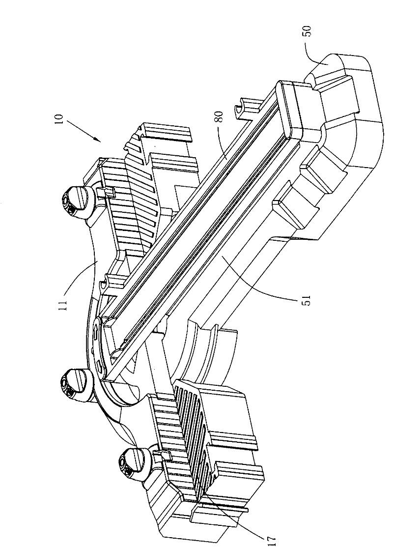
[0075] figure 1 It is a workbench 10 that cooperates with the hand-held cutting machine 1 , and the workbench 10 can support the workpiece to be cut and guide the cutting of the hand-held cutting machine 1 .

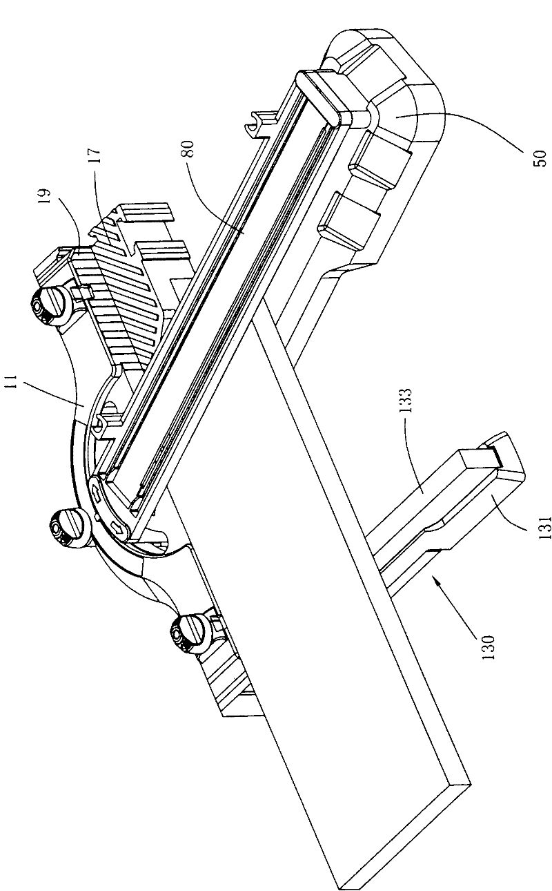
[0076] The workbench 10 includes a base 11 , a rotating arm 50 rotatably connected to the base 11 , and a guide rail 80 supported by the rotating arm 50 . The first support plane 17 of the base 11 and the second support plane 51 on the rotating arm 50 jointly support the workpiece to be cut, and the guide rail 80 is matched with the bottom plate 7 of the hand-held cutting machine 1 to guide the hand-held cutting machine 1 along a predetermined track Cutting the workpiece, the predetermined trajectory is usually a straight line.

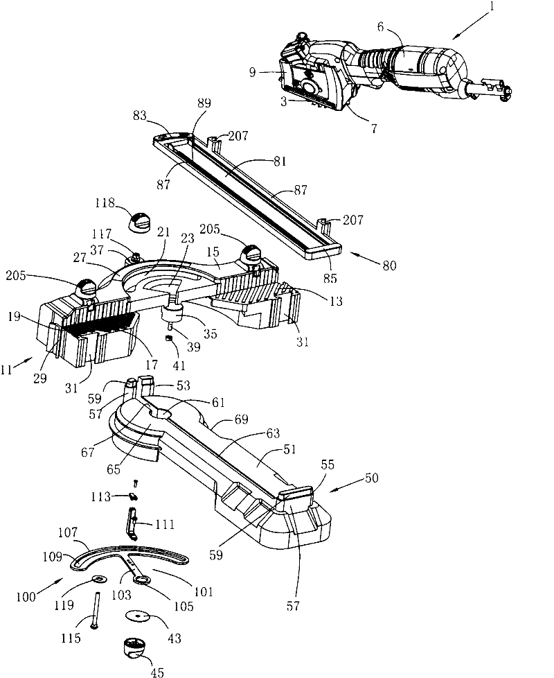
[0077] figure 2 It is an exploded schematic view of the workbench 10 and the matched hand-held cutting machine 1 .

[0078] Such as figure 2 , the hand-held cutting machine 1 includes a working head 3 for processing a workpiece; a motor (n...


PUM


Abstract

The invention relates to a workbench which is used for guiding a handheld cutter. The handheld cutter comprises a working head; the workbench comprises a base, a rotary arm and a guide rail, wherein the base extends along the longitudinal length direction; the rotary arm is pivotally connected with the base; the guide rail is detachably mounted on the rotary arm; on a first position, the guide rail is connected with the rotary arm and used for guiding the handheld cutter, and the distance between a contact surface of the guide rail and a second support plane of the base is constant; and on a second position, the guide rail and the rotary arm are disconnected. As the guide rail and the rotary arm can be disconnected, a workpiece is relatively conveniently to mount and adjust; and moreover,as the distance between the contact surface of the guide rail and the second support plane of the rotary arm is constant, the distance between the guide rail and the rotary arm does not need to be regulated according to the thickness of the workpiece when in work, thus the operation is convenient, the structure of the entire workbench is relatively simple, and the cost is relatively low.

Description

technical field [0001] The invention relates to a workbench, in particular to a workbench for guiding a hand-held cutting machine. Background technique [0002] With hand-held cutting machines, the operator often cuts according to the cutting line marked on the workpiece during use, but due to human factors, the cutting accuracy is relatively low, and the work efficiency cannot be guaranteed. [0003] To this end, technical personnel in the industry have also made improvements. For example, PCT patent application WO2008 / 119580A1 discloses a workbench for guiding a jigsaw. The table includes a base, a swing arm pivotally mounted on the base, and a guide rail for guiding the jig saw. The guide rail is pivotably installed on the rotating arm. After the guide rail pivots upward relative to the rotating arm, the workpiece can be placed on the rotating arm and the base; The locking mechanism locks the guide rail, and then the cutting work can be performed. However, according t...

Claims


Application Information

Patent Timeline
Patent Type & Authority Applications(China)
IPC IPC(8): B23Q9/00B23D47/02B27G5/02
Inventor 沃伦・布朗哈利・索默格雷厄姆・格哈德
Owner POSITEC POWER TOOLS (SUZHOU) CO LTD
Why Eureka
Try Eureka