Locking piece for connecting components

A technology for locking parts and components, applied in mechanical equipment, fixing devices, etc., can solve the problems of easy loosening of components and inability to adjust the size of the locking bayonet, so as to achieve the effect of firm connection and reduced use cost

Inactive Publication Date: 2011-07-20
SHANGHAI ASSAB DISPLAY EQUIP
View PDF5 Cites 10 Cited by
  • Summary
  • Abstract
  • Description
  • Claims
  • Application Information

AI Technical Summary

Problems solved by technology

[0015] The technical problem to be solved by the present invention is to provide a locking piece for component connection in order to overcome the defect that the locking piece in the prior art cannot adjust the size of the locking bayonet, resulting in easy loosening of components after connection

Method used


Image

  • Locking piece for connecting components
  • Locking piece for connecting components
  • Locking piece for connecting components

Examples


Embodiment 1

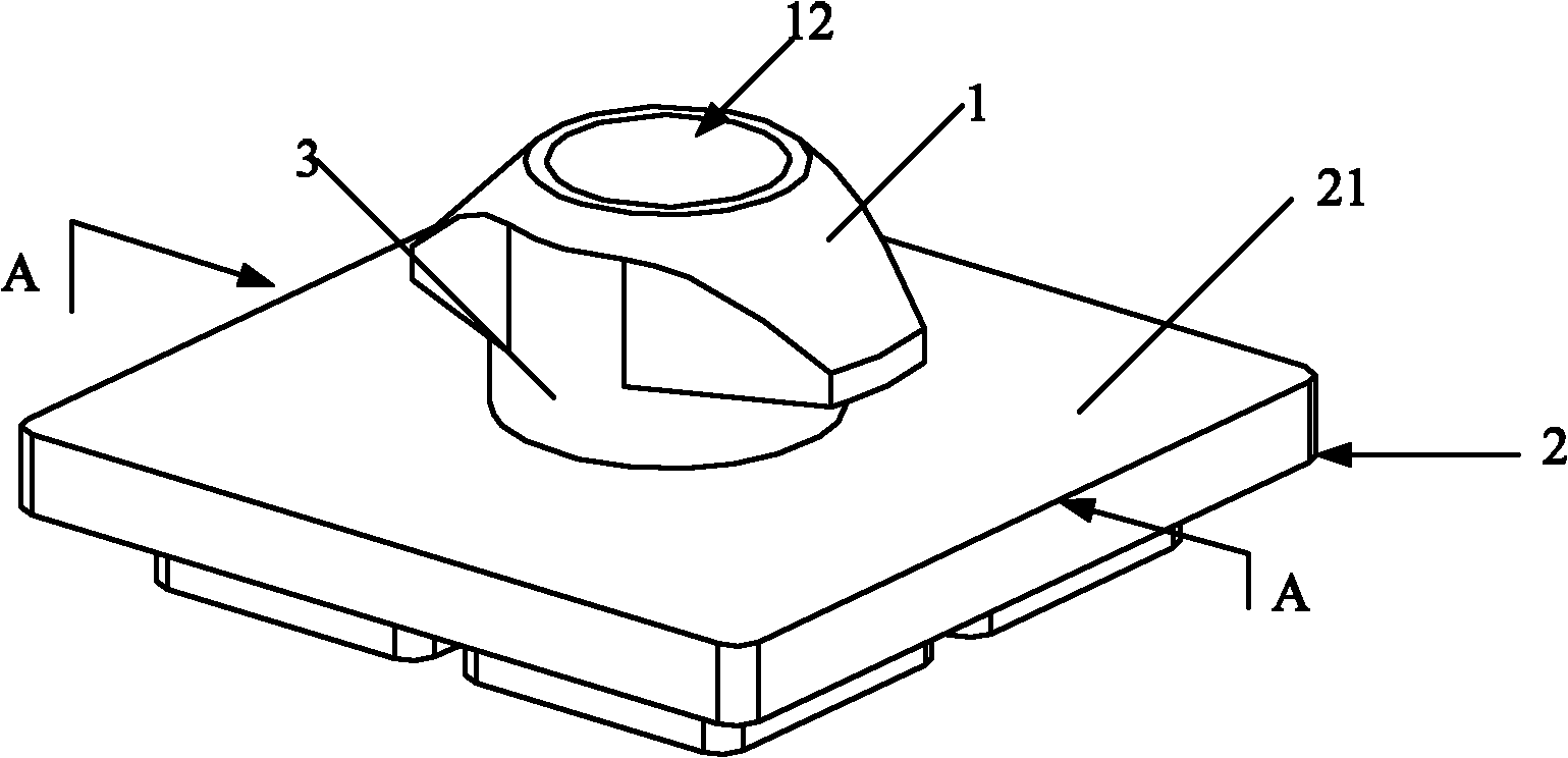
[0066] figure 1 It is a structural perspective view of Embodiment 1 of the present invention.

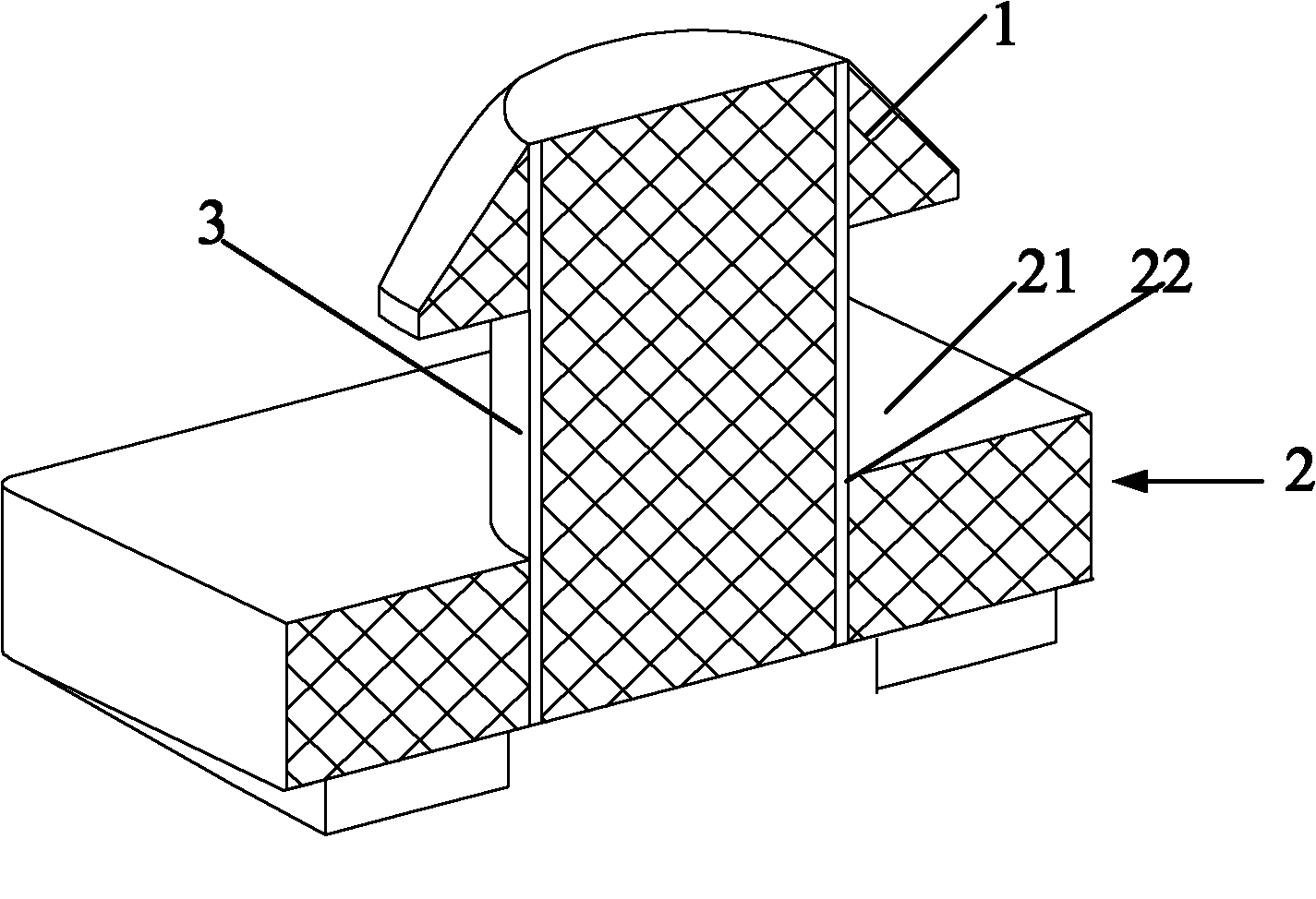
[0067] figure 2 for figure 1 Sectional view along line A-A.

[0068] like figure 1 As shown, the locking part includes a locking head 1 , a locking female part 2 with a bottom plate 21 and a locking column 3 . The locking column 3 is located between the locking head 1 and the bottom plate 21 of the locking female part 2, thereby forming a locking bayonet.

[0069] like figure 2 As shown, the locking head 1 and the locking column 3 are connected by threads, buckled or integrally formed. An appropriate connection method is selected according to the specific strength required by the locking member in actual use.

[0070] Further, the bottom plate 21 of the locking female part 2 is a flat bottom plate. Wherein, a connection hole 22 is provided on the surface of the bottom plate 21 , so that the diameter of the connection hole 22 matches the diameter of the locking post 3 . Th...

Embodiment 2

[0078] Figure 4 It is a front sectional view of Embodiment 2 of the present invention.

[0079] like Figure 4 As shown, the structure of this embodiment is basically the same as that of Embodiment 1, the difference being that a first stepped hole 12 is provided on the top surface of the locking head 1 . The first stepped hole 12 communicates from the top surface of the locking head 1 to the bottom surface of the locking post 3 , and the diameter of the upper hole is larger than the diameter of the lower hole 13 .

[0080] The locking part also includes a locking male part 5 . The locking male part 5 is provided with a through hole 51 penetrating from the top to the bottom, the diameter of which matches the diameter of the lower hole 13 of the first stepped hole 12 .

[0081] Further, the through hole 51 is a second stepped hole, and the diameter of the lower hole is larger than that of the upper hole.

[0082] When it is necessary to change the gap size of the locking ba...

Embodiment 3

[0086] Image 6 It is a structural perspective view of Embodiment 3 of the present invention.

[0087] Figure 7 It is a front sectional view of Embodiment 3 of the present invention.

[0088] like Image 6 and Figure 7 As shown, the structure of this embodiment is basically the same as that of the second embodiment, the difference being that the lower part of the bottom plate 21 of the locking female part 2 is a through space 23 . The locking male part 5 is embedded in the space 23 . The shape of the locking male part 5 matches the space 23, so that the outer walls around the locking male part 5 cooperate with the inner walls of the space 23 to produce frictional locking. The function of this structure is to make the locking male part 5 more firm through frictional locking, so that the locking column 3 will not loosen, and it is convenient to fix and form the required locking bayonet gap. In addition, it is also convenient to connect the locking element to the connecti...


PUM


Abstract

The invention discloses a locking piece for connecting components. The locking piece comprises a locking head and a locking female piece with a bottom plate, wherein a gap-adjustable locking bayonet is formed between the locking head and the bottom plate of the locking female piece. The size of the locking bayonet can be adjusted freely and the locking bayonet is suitable for connecting the components of punching holes with various thicknesses, so that the components can be more firmly connected. Moreover, various locking heads and various locking female pieces can be matched with each other to form the locking piece only by one locking post, so that all the components can be freely combined, and products have more diverse changes, and the using cost is greatly reduced; in addition, the locking head and the bottom plate of the locking female piece can be changed in various shapes and can meet the requirements of connecting various components.

Description

technical field [0001] The invention relates to the technical field of connecting pieces, in particular to a locking piece used for component connection. Background technique [0002] In the advertising exhibition and merchandise display industry, it is often necessary to repeatedly disassemble and assemble the components of the exhibition and display. At present, there are roughly four commonly used methods for locking connections: [0003] 1. Connect and lock the two components of the connection assembly through screws and positioning holes. [0004] 2. Through the principle of expansion nails, the outer wall of the locking member and the inner wall of the connecting component are frictionally locked by rotating the screw. [0005] 3. Cooperate with the spring steel ball and the inlaid spherical crown to make the two parts of the connection assembly connected and locked. [0006] 4. The snap buckle is fixed and locked. A shrapnel is set in one part of the connection ass...

Claims


Application Information

Patent Timeline
Patent Type & Authority Applications(China)
IPC IPC(8): F16B1/04
Inventor 薛翀宇
Owner SHANGHAI ASSAB DISPLAY EQUIP
Why Eureka
Try Eureka