LED (Light-Emitting Diode) lamp bulb with high lighting effect

A technology of LED light bulbs and high light efficiency, which is applied in the field of LED lamps, can solve the problems of reducing the brightness of LED light bulbs and low light efficiency of LED light bulbs, and achieve the effect of improving brightness

Inactive Publication Date: 2011-07-20
美迅(南京)生态农业开发有限公司
View PDF7 Cites 8 Cited by
  • Summary
  • Abstract
  • Description
  • Claims
  • Application Information

AI Technical Summary

Problems solved by technology

[0004] However, if figure 1 As shown, the LED luminous column 101 of the LED light bulb in the prior art is mostly perpendicular to the connection line 103 between its center line and the center of the heat dissipation substrate 102, that is, the angle between the connection line 103 and the LED luminous column 101 is 90 degrees. The arrangement of the LED luminous column 101 of the light bulb on the heat dissipation substrate 102 makes the LED luminous column 101 all face the center of the heat dissipation substrate 102, as figure 2 As shown, when the LED light-emitting column 101 emits light, most of the light directed toward the center of the heat dissipation substrate 102 will cancel each other, thereby reducing the brightness of the entire LED bulb, that is, the light efficiency of the LED bulb is not high

Method used


Image

  • LED (Light-Emitting Diode) lamp bulb with high lighting effect
  • LED (Light-Emitting Diode) lamp bulb with high lighting effect
  • LED (Light-Emitting Diode) lamp bulb with high lighting effect

Examples


Embodiment 1

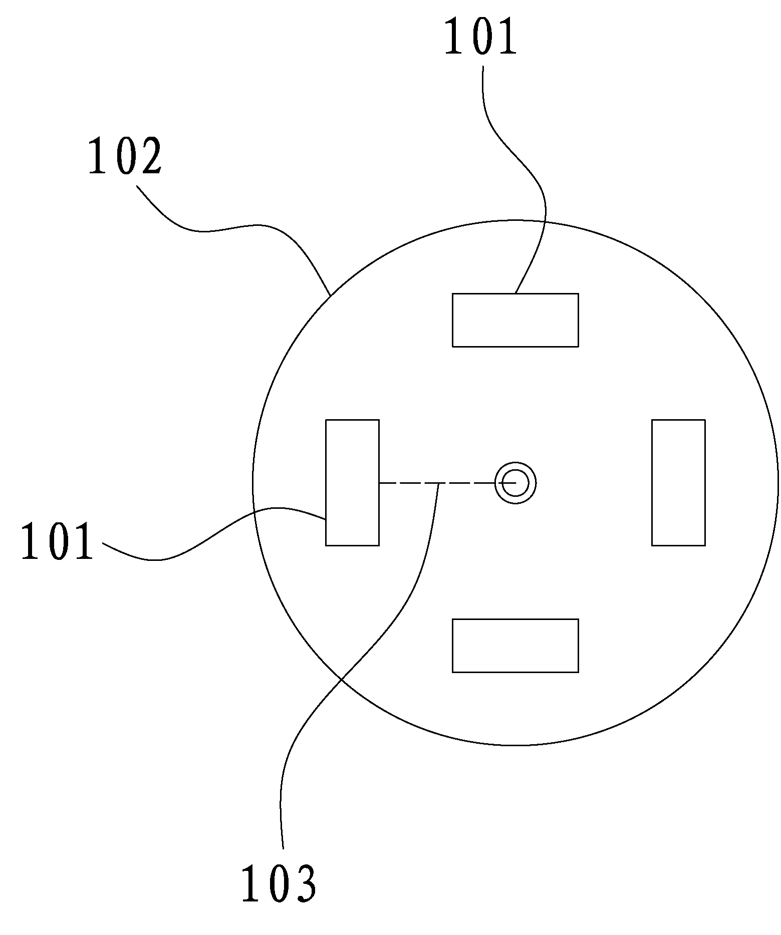
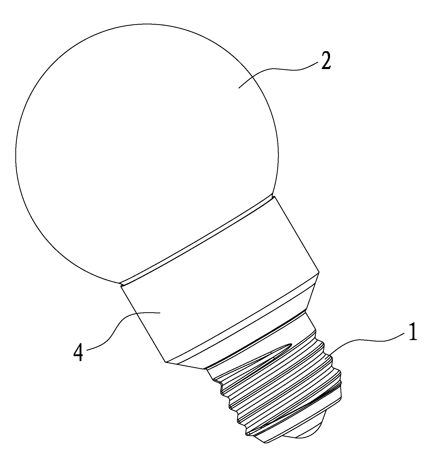
[0039] A kind of high luminous efficiency LED light bulb of the present invention, as Figure 3-11 As shown, it includes a lamp cap 1, a lampshade 2, and a power supply 3. The lampshade 2 is installed on the top of the lamp cap 1, the power supply 3 is located in the lamp cap 1, and the power supply 3 is electrically connected with the lamp cap 1, so that the power supply 3 can be externally connected to an alternating current through the lamp cap 1, wherein A heat dissipation metal shell 4 is clamped between the lamp holder 1 and the lampshade 2, the top of the heat dissipation metal shell 4 is located in the lampshade 2, and the top of the heat dissipation metal shell 4 is clamped and fixed with a heat dissipation substrate 5, and the heat dissipation substrate 5 is plugged and fixed with an LED The light-emitting column 6, the heat generated when the LED light-emitting column 6 emits light can be transferred to the heat-dissipating metal shell 4 through the heat dissipation ...

Embodiment 2

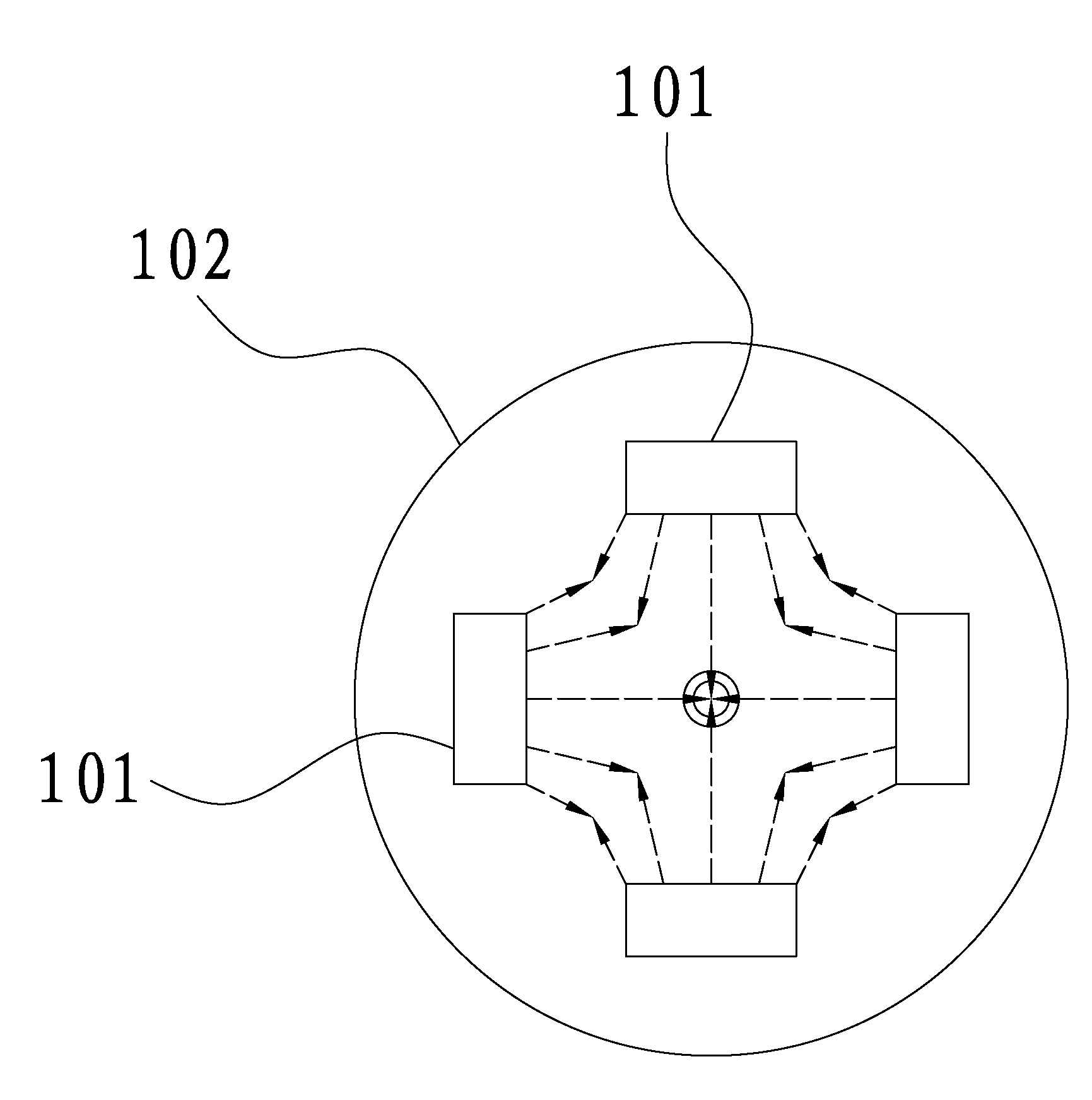
[0047] Embodiment 2 of a high luminous efficiency LED light bulb of the present invention, as Figure 12 As shown, the difference between this embodiment and Embodiment 1 is that the number of LED light-emitting columns 6 is five, of course, the number of LED light-emitting columns 6 can also be other numbers such as three, six, etc., as long as they are relatively Rotate and place at the center of the heat dissipation substrate 5 to form a whirlwind arrangement with the center of the heat dissipation substrate 5 as the midpoint, and increase the brightness of the LED light bulb. Other structures and working principles of this embodiment are the same as those of Embodiment 1, and will not be repeated here.


PUM


Abstract

The invention relates to an LED (Light-Emitting Diode) lamp technology, in particular to an LED lamp bulb with high lighting effect, comprising a lamp head, a lamp shade and a power supply, wherein a radiating metal shell is clamped between the lamp head and the lamp shade; the top of the radiating metal shell is positioned in the lamp shade; a radiating substrate is clamped and fixed at the top of the radiating metal shell; LED light-emitting columns are plugged in and fixed on the radiating substrate and are uniformly arranged at intervals; and the LED light-emitting columns are arranged ina rotating way relative to the center of the radiating substrate. As the LED light-emitting columns are arranged in a rotating way relative to the center of the radiating substrate, counteracting of large parts of light rays among the LED light-emitting columns can be avoided, and the light rays emitted by the LED light-emitting columns are fully utilized, so that the brightness of the whole LED lamp bulb is improved and the LED lamp bulb with high lighting efficiency is realized.

Description

technical field [0001] The invention relates to LED lamp technology, in particular to a high-luminous-efficiency LED light bulb. Background technique [0002] Because LED (Light Emitting Diode, light-emitting diode) has the characteristics of long service life, low energy consumption, and significant energy saving, LED has been widely used as a light source in daily life, such as cup lights, spotlights, car lights, LED Light bulbs and other LED lighting fixtures. [0003] At present, LED light bulbs generally include a lamp cap, a lampshade installed on the top of the lamp cap, and a power supply located in the lamp cap. An LED light-emitting column is arranged in the lampshade. The LED light-emitting column is electrically connected to the power supply in the lamp cap, and the LED light-emitting column is fixed on the heat dissipation substrate. When the LED light-emitting column is energized to emit light, the light emitted by it can be irradiated through the lampshade to...

Claims


Application Information

Patent Timeline
Patent Type & Authority Applications(China)
IPC IPC(8): F21S2/00F21V19/00F21V29/00F21V23/00F21V17/10F21Y101/02F21K9/232F21V29/70F21V29/89F21Y107/40F21Y115/10
Inventor 伍治华谢伊明林日辉邵小兵
Owner 美迅(南京)生态农业开发有限公司
Why Eureka
Try Eureka