Rotary converter

A converter and rotating mechanism technology, applied in the direction of rotary drum furnace, furnace, furnace type, etc., can solve the problems of bulky drive mechanism, large space occupation, waste of resources, etc., and achieve good reaction effect, sufficient raw material mixing, and precise control Effect

Inactive Publication Date: 2011-07-20
CHINA ENFI ENGINEERING CORPORATION
View PDF6 Cites 4 Cited by
  • Summary
  • Abstract
  • Description
  • Claims
  • Application Information

AI Technical Summary

Problems solved by technology

In addition, the traditional rotary converter uses a high-speed motor and a reducer to drive the rotation of the converter. The disadvantage is that the drive mechanism is bulky and heavy, takes up a lot of space, and wastes resources.

Method used


Image

  • Rotary converter
  • Rotary converter
  • Rotary converter

Examples


Embodiment Construction

[0026] Embodiments of the present invention are described in detail below, examples of which are shown in the drawings, wherein the same or similar reference numerals designate the same or similar elements or elements having the same or similar functions throughout. The embodiments described below by referring to the figures are exemplary only for explaining the present invention and should not be construed as limiting the present invention.

[0027] In the description of the present invention, the orientation or positional relationship indicated by the terms "inside", "outside", "upper", "lower", "top", "bottom" etc. are based on the orientation or positional relationship shown in the drawings, The disclosure is merely for convenience in describing the invention and does not require that the invention must be constructed and operated in a particular orientation, and thus should not be construed as limiting the invention.

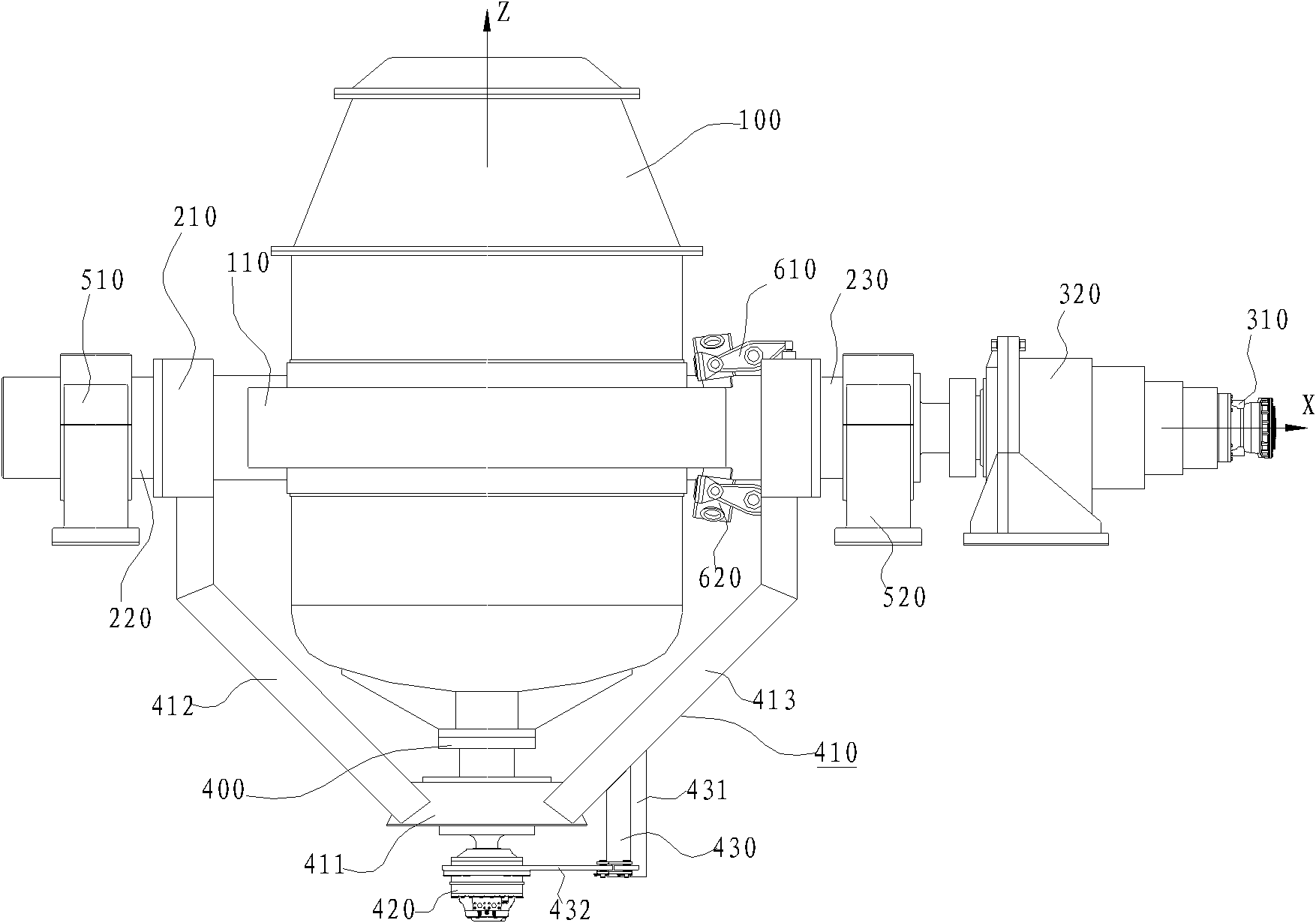
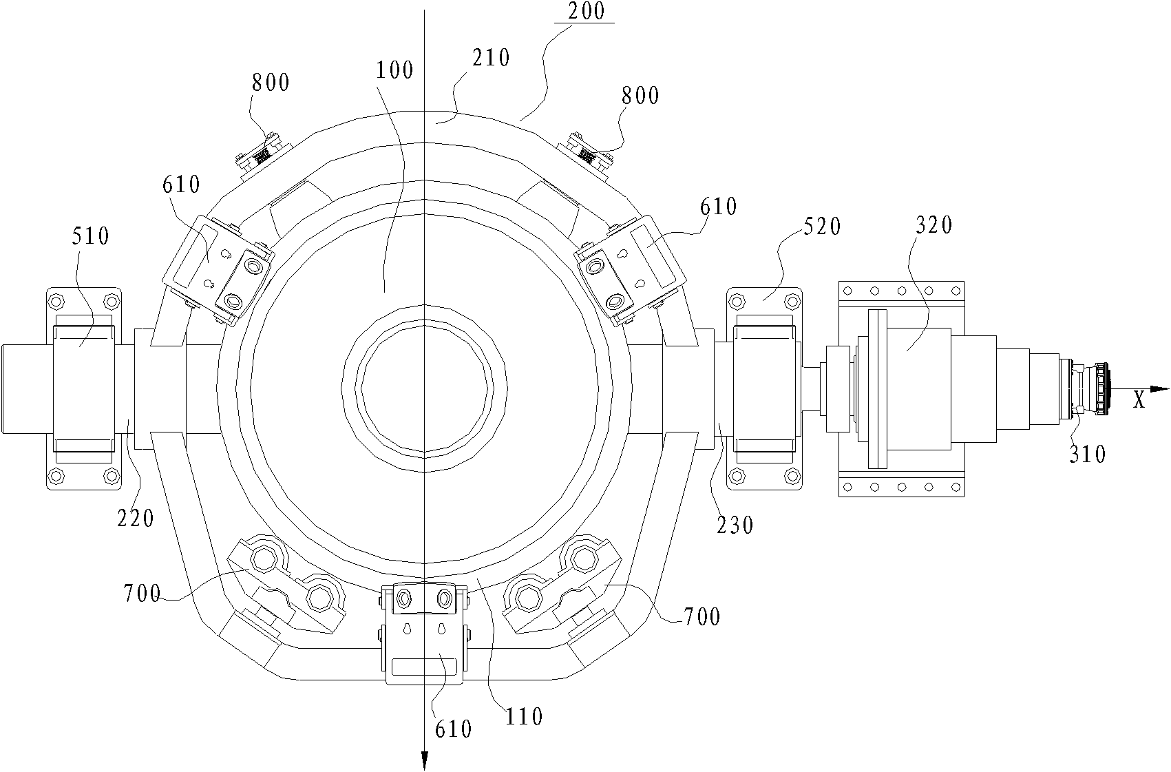
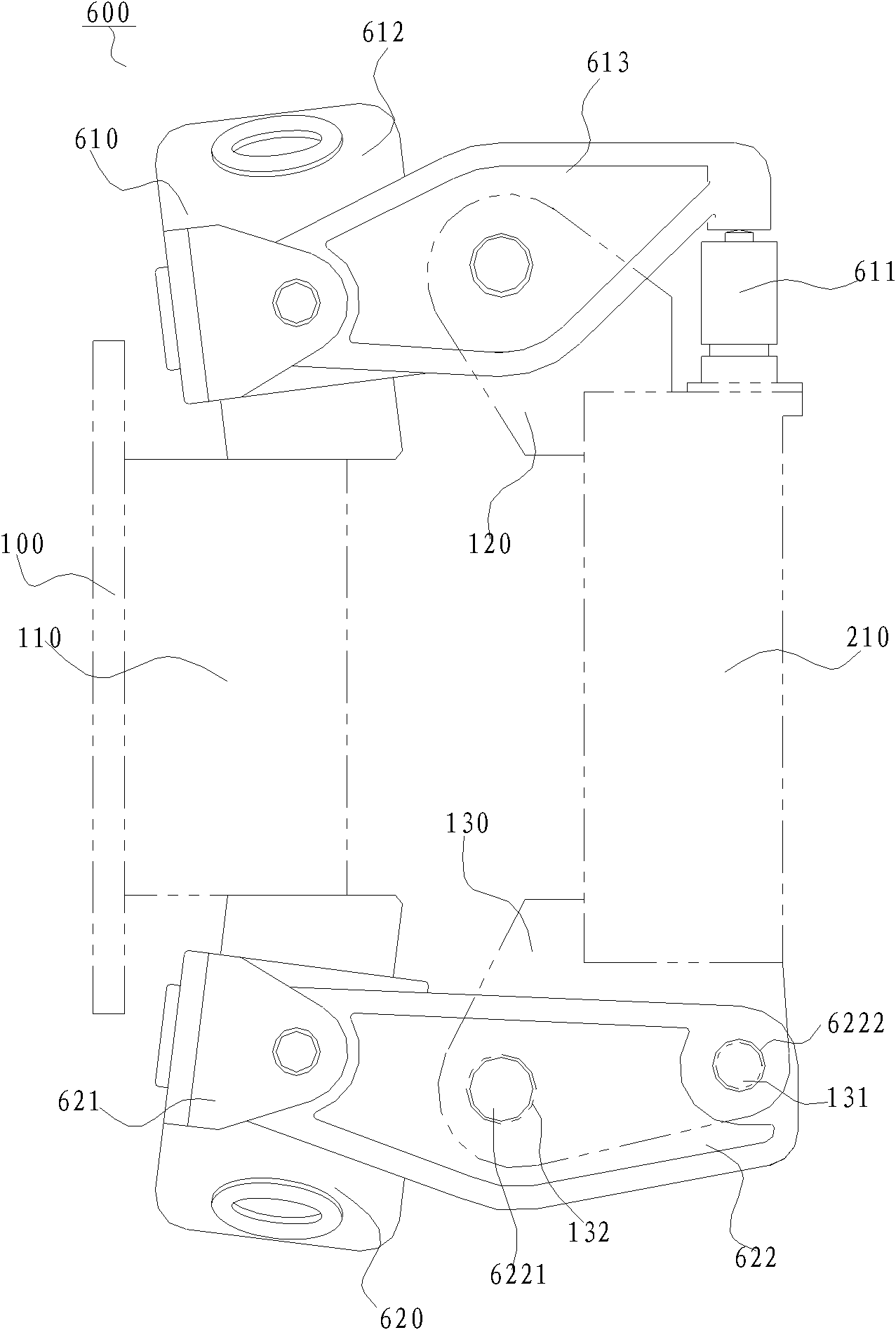
[0028] Refer below Figure 1-Figure 4 A rotary conve...


PUM


Abstract

The invention discloses a rotary converter, which comprises a furnace body, a bracket component, a first rotating mechanism, a second rotating mechanism, a first supporting seat and a second supporting seat, wherein the periphery of the furnace body is provided with a rolling ring; the bracket component comprises a supporting ring, and a first trunnion and a second trunnion arranged on the peripheral side of the supporting ring; the supporting ring can support the rolling ring in a relative moving way to support the furnace body; the first rotating mechanism is connected with the bracket component to drive the bracket component and the furnace body to tilt around an X axis; the second rotating mechanism is arranged on the bracket component and is used for driving the furnace body to rotate relative to the bracket component around a Z axis; and the first supporting seat and the second supporting seat rotationally support the first trunnion and the second trunnion respectively. The rotary converter according to the embodiment of the invention can rotate around the Z axis and tilt around the X axis, reaction raw materials are added into the furnace body from a furnace mouth when the furnace body is in a standing state, and the furnace body tilts forwards or backwards around the X axis by a preset tilt angle and can rotate around the Z axis at the same time in the working process, so that the raw materials in the furnace body are mixed more fully and a better reaction effect is achieved.

Description

technical field [0001] The invention relates to the field of nonferrous smelting, in particular to a rotary converter. Background technique [0002] The traditional rotary converter usually rotates around the axis of its furnace body, so that various raw materials can be further mixed to achieve better reaction effect while being treated at high temperature in the furnace body. In addition, the traditional rotary converter uses a high-speed motor and a reducer to drive the rotation of the converter. The disadvantage is that the drive mechanism is bulky and heavy, takes up a lot of space, and wastes resources. Contents of the invention [0003] The present invention aims to solve at least one of the technical problems existing in the prior art. [0004] Therefore, an object of the present invention is to provide a rotary converter, which can rotate around the Z axis and tilt around the X axis at the same time, so that the reaction materials in the furnace can be mixed more...

Claims


Application Information

Patent Timeline
Patent Type & Authority Applications(China)
IPC IPC(8): F27B7/22F27B7/26
Inventor 曹珂菲张振民邬传谷冯双杰崔大韡
Owner CHINA ENFI ENGINEERING CORPORATION
Why Eureka
Try Eureka