Force-transmitting device with a calibration weight that can be coupled and uncoupled

A technology for transferring devices and calibrating weights, which can be used in measuring devices, weighing equipment testing/calibration, weighing, etc., and can solve problems such as high cost

Active Publication Date: 2011-07-20
METTLER TOLEDO INC
View PDF10 Cites 10 Cited by
  • Summary
  • Abstract
  • Description
  • Claims
  • Application Information

AI Technical Summary

Problems solved by technology

The contact points between the calibration weight and the calibration weight carrier arm or between the sharp-edged pivot and the support block are thus made with the highest precision, resulting in a correspondingly high cost

Method used


Image

  • Force-transmitting device with a calibration weight that can be coupled and uncoupled
  • Force-transmitting device with a calibration weight that can be coupled and uncoupled
  • Force-transmitting device with a calibration weight that can be coupled and uncoupled

Examples


Embodiment Construction

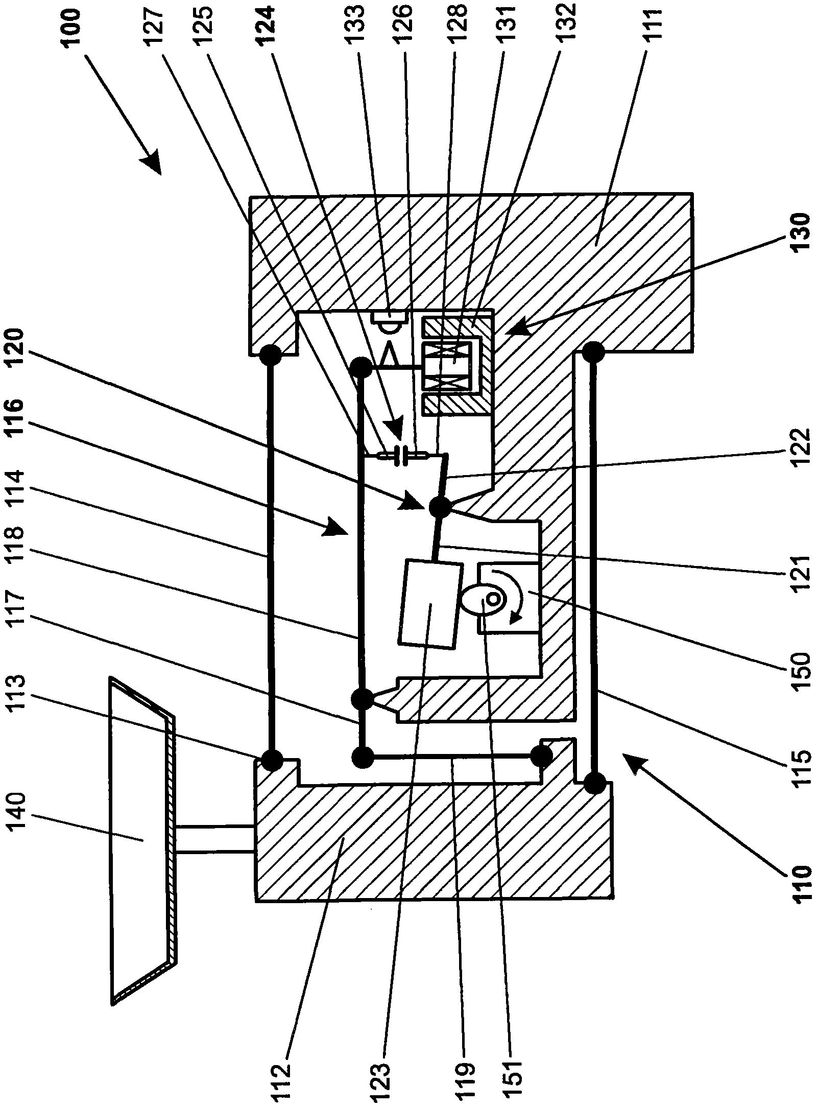
[0040] figure 1 A schematic side view of a weighing cell 100 with a force transmission device 110 of the first embodiment is shown. The force transmission device 100 has a stationary part 111 and a load receiving part 112 . The load receiving part 112 is guided in parallel motion by being connected to the stationary part 111 by a first parallel guide 114 and a second parallel guide 115 . All pivotal connections 113 of the force transfer device 110 are pictorially represented by solid black circles in the figure and may be implemented in any known design in the prior art. These pivot connections 113 are usually designed as Figure 5-7 This flexure pivot is shown in .

[0041] A load receiving member 140 in the form of a weighing pan is connected to the load receiving part 112 . Furthermore, a measuring transducer 130 capable of generating a force-dependent weighing signal is rigidly mounted on the stationary part 111 . The measuring transducer 130 shown in the figure has a...


PUM


Abstract

A force-transmitting device for a gravimetric measuring instrument has a load-receiving part and a stationary part. The load-receiving part is force-transmitting linked either directly or by way of at least one coupling element and at least one lever to a measurement transducer which is arranged on the stationary part. The force-transmitting device further includes a calibration lever whose fulcrum is based on the stationary part. The calibration lever includes a first and a second calibration lever arm, wherein the first calibration lever arm is solidly connected to a calibration weight, while the second calibration lever arm is connected by way of a unidirectional coupling element to the load-receiving part, or to the at least one coupling element, or to a lever arm of the at least one lever. The unidirectional coupling element is divided in two, i.e. into a first coupling element part and a second coupling element part, thus the force transmitted by the unidirectional coupling element is only tensile or compressive force because of the divided design.

Description

technical field [0001] The invention relates to a force transmission device for a gravimetric measuring instrument, wherein the force transmission device has a load-receiving part and a stationary part. A weighing pan connected to the load receiving part receives the load to be weighed. The force exerted by the load on the weighing pan is transmitted to the measuring transducer either directly or by means of a reducing lever mechanism. Together with the parallelogram-type guide structure for guiding the weighing pan and the load-receiving part in their vertical movement, the force transmission device and the measuring transducer essentially constitute the weighing cell of the gravimetric measuring instrument. Background technique [0002] The prior art discloses weighing cells based on various operating principles, such as weighing cells with strain gauges, weighing cells with string oscillators or electromagnetic force compensation (EMFC) weighing cells. Gravimetric measu...

Claims


Application Information

Patent Timeline
Patent Type & Authority Applications(China)
IPC IPC(8): G01G23/01
CPCG01G21/00
Inventor H-R·伯克哈特F·施奈德D·热努
Owner METTLER TOLEDO INC
Why Eureka
Try Eureka