Method for realizing distributed protection and passive optical network (PON) system

A passive optical network, distributed technology, applied in the field of communication, can solve the problems of increased protection switching service recovery time, short service interruption time, PON protection function failure, etc., to eliminate protection switching time bottlenecks, shorten recovery time, and improve The effect of business protection capabilities

Active Publication Date: 2011-07-20
ZTE CORP
View PDF4 Cites 10 Cited by
  • Summary
  • Abstract
  • Description
  • Claims
  • Application Information

AI Technical Summary

Problems solved by technology

There are defects in this method. First, in the centralized protection mode, the protection functions are all implemented on the main control switch board, and OLT equipment usually has only one working main control switch board. If there is only one main control switch board An abnormality of the board will lead to complete failure of the PON protection function; secondly, the service interruption time (protection switching service recovery time) required by the current operator due to PON protection switching is very short, and the traditional centralized protection mode line card needs to be When an inter-board message is sent, the alarm is reported to the main control switch board, so there is a scheduling delay for the main control switch board to report the alarm message on th

Method used


Image

  • Method for realizing distributed protection and passive optical network (PON) system
  • Method for realizing distributed protection and passive optical network (PON) system
  • Method for realizing distributed protection and passive optical network (PON) system

Examples


Example Embodiment

Specific embodiment one:

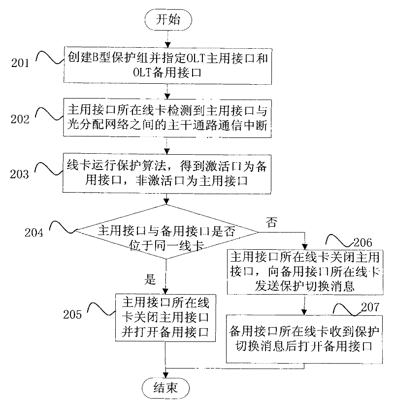
[0061] In Type B protection mode, the network connection between OLT equipment and ONU equipment is as follows: Figure 4 As shown, the OLT device includes a main control switch board and multiple line cards, where the OLT interface 1 and OLT interface 2 of the line card 1 communicate with the ONU through the N:2 optical splitter 1 11 to ONU 1N Connected, OLT interface 4 of line card 1 and OLT interface 4 of line card N connect to ONU through N:2 optical splitter 221 to ONU 2N The distributed protection of the B-type protection group is realized by the following steps:

[0062] Step 1: Create B-type protection group P1, set OLT interface 1 of line card 1 as the active interface, set OLT interface 2 of line card 1 as the standby interface (at this time, the active interface is turned on and the standby interface is turned off), and the active interface The communication service carried by the network is normal, and the standby interface is in the co...

Example Embodiment

Specific embodiment two:

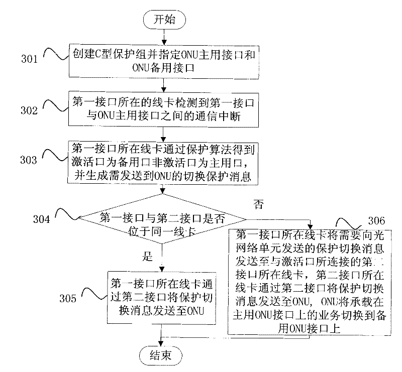
[0068] In the Type C protection scenario, the network connection between the OLT and the ONU is as follows: Figure 5 As shown, the OLT device includes a main control switch board and multiple line cards, the OLT interface 1 of the line card 1 is connected to the ONU interface 1 of the ONU device 1 through the N:1 optical splitter 1, and the OLT interface 2 of the line card 1 is connected through the The N:1 optical splitter 2 is connected to the ONU interface 2 of the ONU device 1, the OLT interface 4 of the line card 1 is connected to the ONU interface 1 of the ONU device 3 through the N:1 optical splitter 3, and the OLT interface 1 of the line card N is connected to the N :1 The optical splitter 4 is connected to the ONU interface 2 of the ONU device 3 . The distributed protection of the C-type protection group is implemented by the following steps:

[0069] Step 1: Create a C-type protection group P1, set ONU interface 1 of ONU device 1 as the a...


PUM


Abstract

The invention provides a method for realizing distributed protection and a passive optical network (PON) system. The method comprises a step that: after detecting damage of a master interface or interruption of a service born on the master interface, a line card of an optical line terminal carries out protection switching to switch the communication service born on the master interface to a slave interface. According to the distributed protection method provided by the invention, a protection function of the PON is transferred to the line card from a main control switch board, and the line card performs detection alarming, operates a protection algorithm and carries out protection switching operation, so that the problem of single-point failure caused by using the unique main control switch board to realize PON protection in a centralized protection method is solved, a bottleneck for protection switching time in a centralized protection mode can be eliminated, recovery time for service protection is shortened, the service protection capacity of the optical line terminal is improved, and the requirement of an operator is further met.

Description

technical field [0001] The present invention relates to the technical field of communication, in particular to a method for realizing distributed protection in a passive optical network (Passive Optical Networks, PON for short) and a passive optical network system. Background technique [0002] The passive optical network includes an Ethernet passive optical network (Ethemet PON, EPON for short), a gigabit PON (GPON for short), a next generation optical passive network (Next Generation PON, NG-PON), and the like. The passive optical network adopts a point-to-multipoint optical fiber access technology, which consists of the optical line terminal (Optical Line Terminal, OLT for short), the optical network unit (Optical Network Unit, ONU for short) on the user side, and the connection between the OLT and the ONU. Optical Distribution Network (ODN for short) composition. The protection mechanism of the passive optical network is mainly used to enhance the reliability of the opt...

Claims


Application Information

Patent Timeline
IPC IPC(8): H04B10/08H04B1/74H04Q11/00
CPCH04J3/14H04Q2011/0081H04Q11/0067H04J3/1694
Inventor 陈洁云卢金树黄文杰
Owner ZTE CORP
Why Eureka
Try Eureka