Flexible coupling structure and ship thruster device with same

A coupling and thrust technology, which is applied to ship propulsion, elastic couplings, propulsion transmission devices, etc., can solve problems such as large influence, poor rotation balance accuracy, and large unbalanced force, so as to save production costs, The effect of preventing lateral vibration

Inactive Publication Date: 2013-04-10
KAWASAKI HEAVY IND LTD
View PDF1 Cites 0 Cited by
  • Summary
  • Abstract
  • Description
  • Claims
  • Application Information

AI Technical Summary

Problems solved by technology

When the outer cylinder 4 is short, the accuracy of the rotational balance is poor, that is, even the outer cylinder 4 with a large degree of unbalance rarely becomes a problem
[0010] Moreover, the longer the length, the heavier the weight, and the greater the degree of unbalance, so the unbalanced force becomes larger, and there is a problem of lateral vibration during rotation due to the unbalanced moment.
In particular, vibration problems rarely occur in machines with low speeds of several tens of revolutions per minute (rpm), but in the case of machines with medium speeds of hundreds of revolutions per minute or more and high speed machines higher than that, the effect is significant. big problem

Method used


Image

  • Flexible coupling structure and ship thruster device with same
  • Flexible coupling structure and ship thruster device with same
  • Flexible coupling structure and ship thruster device with same

Examples


Embodiment Construction

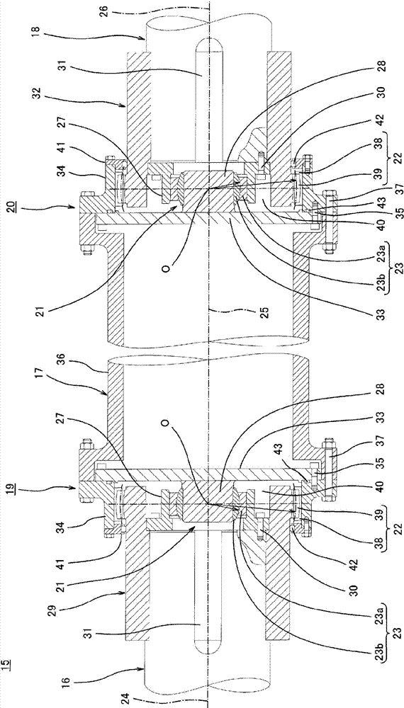
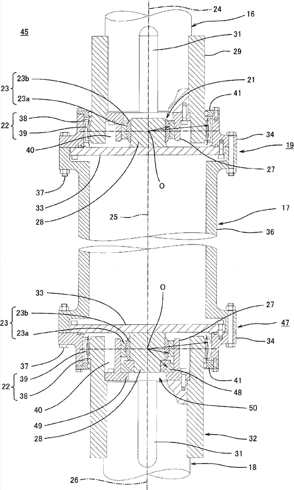
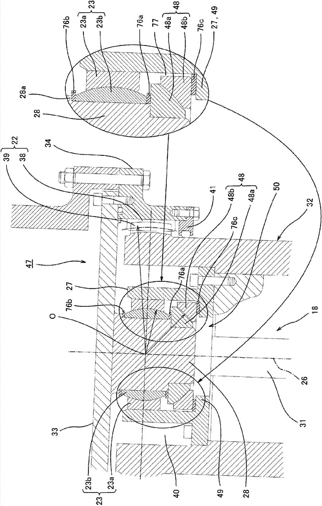
[0062] The first embodiment

[0063] Refer below figure 1 The first embodiment of the flexible coupling structure of the present invention will be described. figure 1 The flexible coupling 15 shown, through the first flexible coupling structure 19, the connecting shaft 17, the second flexible coupling structure 20, and the driven shaft 18, will serve as a drive unit (not The rotation of the drive-side shaft 16 provided in the figure is transmitted to the propeller of a ship propulsion (not shown). The driving shaft 16, the first flexible coupling structure 19, the connecting shaft 17, the second flexible coupling structure 20, and the driven shaft 18 are arranged substantially horizontally.

[0064] In addition, the connecting shaft 17 has a relatively long size and rotates at a rotation speed of, for example, several hundred revolutions per minute or higher. The driving shaft 16 is rotatably provided in the driving part, and the driven shaft 18 is rotatably provided in the thru...


PUM


Abstract

The present invention provides a self load supporting type flexible coupling structure, that is, a self-contained type flexible coupling structure configured such that a vibration problem does not occur in the flexible coupling structure which is large in total length. The present invention is configured such that: a radial spherical bearing portion (23) and a thrust spherical bearing portion (48) are incorporated in a gear coupling structure such that rotational center positions of the radial spherical bearing portion (23) and thrust spherical bearing portion (48) coincide with a crowning center position (O) of an outer gear (39); an inner gear (38) is supported by the radial spherical bearing portion (23) and the thrust spherical bearing portion (48); and the outer gear (39) is able to incline relatively with respect to the inner gear (38) based on the crowning center position (O).

Description

Technical field [0001] The present invention relates to a flexible coupling structure that connects a drive-side shaft and a driven shaft and can transmit rotation and power of the drive-side shaft to the driven shaft, and a marine propulsion device having such a structure. Background technique [0002] Traditionally, in the case of transmitting the power of the driving prime mover to the driven machine, in order to be able to tolerate the deviation of the shaft during installation, a flexible coupling structure is usually installed in between for power transmission. In this way, there is no need to worry about the installation accuracy of the prime mover and the driven machine, and the installation work can be completed in a short time. [0003] On the other hand, especially for ships, the installation reference foundation (hull) will have some changes due to deformation and other reasons, even if there are subtle changes in the axis of the two machines, as long as the flexible co...

Claims


Application Information

Patent Timeline
Patent Type & Authority Patents(China)
IPC IPC(8): F16D3/18B63H23/04
CPCB63H23/321F16D3/185B63H23/04F16D3/18
Inventor 日野满伸
Owner KAWASAKI HEAVY IND LTD
Why Eureka
Try Eureka