Lighting device

A light-emitting device and light-emitting mechanism technology, applied in the direction of lighting devices, light sources, components of lighting devices, etc., can solve problems such as large structural forms, achieve compact structure, high safety requirements, and improve the effect of electrical insulation

Active Publication Date: 2011-07-20
LEDVANCE GMBH
View PDF5 Cites 0 Cited by
  • Summary
  • Abstract
  • Description
  • Claims
  • Application Information

AI Technical Summary

Problems solved by technology

Up to now, these distances have mostly been observed by the corresponding distance between the primary side and the secondary side (in particular the cooling body), but this results in a comparatively large design

Method used


Image

  • Lighting device
  • Lighting device
  • Lighting device

Examples


Embodiment Construction

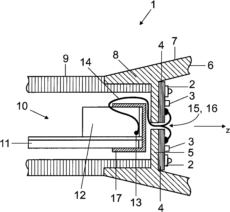
[0028] figure 1 The LED lighting device 1 according to the first embodiment is shown. The device has a plurality of light-emitting diodes 2 which are mounted together with associated electronic components 3 on the upper side of a printed circuit board 4 . The electronics provide at least one driver for feeding the light-emitting diodes in a controlled manner. In order to dissipate heat from the light-emitting diodes 2 and the electronic components 3 , the printed circuit board 4 is embodied as a metal-core printed circuit board, which is placed with its bottom side on the planar mounting area 5 of the metal heat sink 6 . The mounting area 5 is surrounded laterally by a surrounding side wall 7 which (to the right of the mounting area 5 , in the z direction) together with the mounting area 5 forms a cup shape for the light emitted by the LED 2 reflector. Below the placement area 5 (in relation to the z-direction), the surrounding side walls 7 form a connection area 8 for ins...


PUM


Abstract

The present invention relates to a lighting device (1,18,22,24,27) of the present invention comprising at least one lighting means (2), a power supply unit (10) for the at least one lighting means (2), and a cooling body (6) for cooling the at least one lighting means (2), wherein the at least one lighting means (2) is fastened to the cooling body (6) and is separated from the power supply unit (10) by the cooling body (6), and wherein the power supply unit (10) comprises an electrically insulating cap (17,19,23,25,29), which is attached at least partially over the power supply unit (10) and separates the power supply unit from the cooling body (6).

Description

technical field [0001] The invention relates to a lighting device having at least one lighting means, a power supply unit for the at least one lighting means and a heat sink for cooling the at least one lighting means. Background technique [0002] One of the main problems when shrinking illuminants with light-emitting diodes is the distance that must be observed between the primary side and the secondary side of the associated power supply. The separation is necessary because the light-emitting diodes are placed electrically conductively on the cooling body and therefore in most cases on the accessible metal body. Typically, the primary side refers to all primary components and the transformer core. The required distances between primary-side and secondary-side components are, for example, 6.5 mm (air gap) and 5 mm (creepage distance) according to DIN EN 60598-1 or VDE 0711-1. To date, these distances have mostly been observed by corresponding spacings of the primary side...

Claims


Application Information

Patent Timeline
Patent Type & Authority Applications(China)
IPC IPC(8): F21K99/00
CPCF21V23/002F21K9/00F21Y2101/02F21V23/02F21Y2115/10F21V23/00
Inventor 法比安·赖因格鲁贝尔
Owner LEDVANCE GMBH
Why Eureka
Try Eureka