Cooling device for cooling a laser arrangement and laser system comprising cooling devices

a cooling device and laser system technology, applied in semiconductor lasers, semiconductor/solid-state device details, lighting and heating apparatus, etc., can solve the problems of high cost, and achieve the effect of simplifying the scalability of the laser system

Active Publication Date: 2017-01-31
TRUMPF PHOTONIC COMPONENTS GMBH
View PDF20 Cites 0 Cited by
  • Summary
  • Abstract
  • Description
  • Claims
  • Application Information

AI Technical Summary

Benefits of technology

[0006]It's thus an object of the present invention to provide an improved cooling device for cooling a laser arrangement enabling simplified scalability of a laser system comprising at least two cooling devices. It's a further an object to provide a corresponding method of manufacturing such a cooling device and laser system.
[0008]The arrangement of the first and second coolant supply through hole in combination with the coupling element of the cooling device enables an easy scalability of a laser system comprising two, three, four or more cooling devices with laser arrangements mounted on the mounting areas. Furthermore, no complex water distribution plate consisting of corrosion resistant material with high precision drillings for mounting coolers has to be provided, which has to be manufactured individually thus causing high costs. The cooling device may enable laser systems of different size at reduced costs.
[0014]At least one slot may be arranged on a first side of the cooling device extending in parallel to the extension of the first and the second coolant supply through hole and at least one key may be arranged on a second side of the cooling device orientated in parallel to the extension of the first and the second coolant supply through hole. The arrangement of slot and key on the first and second side and thus opposite sides of the cooling device may enable a reliable arrangement of more than two cooling devices. In addition only one type of cooling devices is needed in order to enable scalability thus reducing costs.
[0032]The coupling element and the arrangement of the first and second coolant supply through hole enable a simplified scalability of laser systems comprising such cooling devices.
[0041]The method may enable a scalable laser system with reduced requirements with respect to the material used for the base plate because the base plate is not used as water distribution plate. In addition an easy alignment of the cooling devices and thus the laser arrangements may be enabled by enabling to couple the cooling devices first and subsequently couple the base plate. No high precision drillings may be needed in the base plate.

Problems solved by technology

Furthermore, no complex water distribution plate consisting of corrosion resistant material with high precision drillings for mounting coolers has to be provided, which has to be manufactured individually thus causing high costs.

Method used


Image

  • Cooling device for cooling a laser arrangement and laser system comprising cooling devices
  • Cooling device for cooling a laser arrangement and laser system comprising cooling devices
  • Cooling device for cooling a laser arrangement and laser system comprising cooling devices

Examples


Embodiment Construction

[0062]Various embodiments of the invention will now be described by means of the figures.

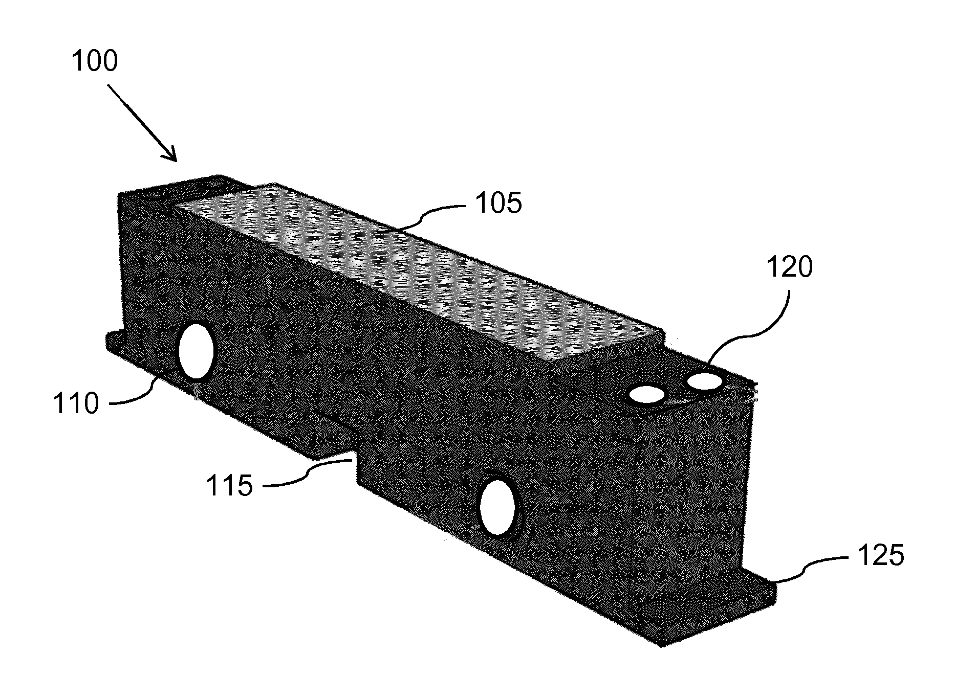
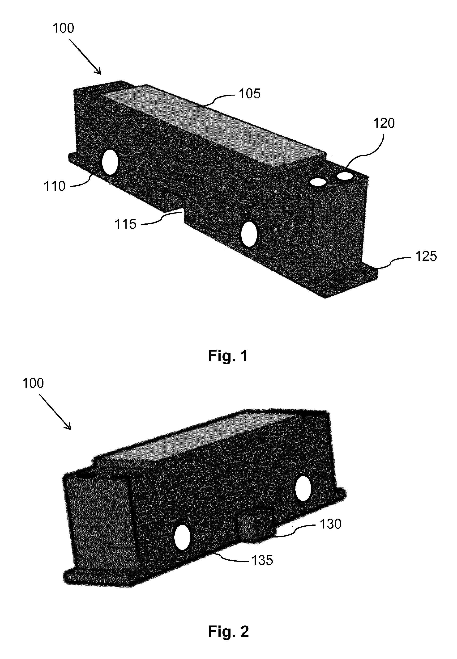
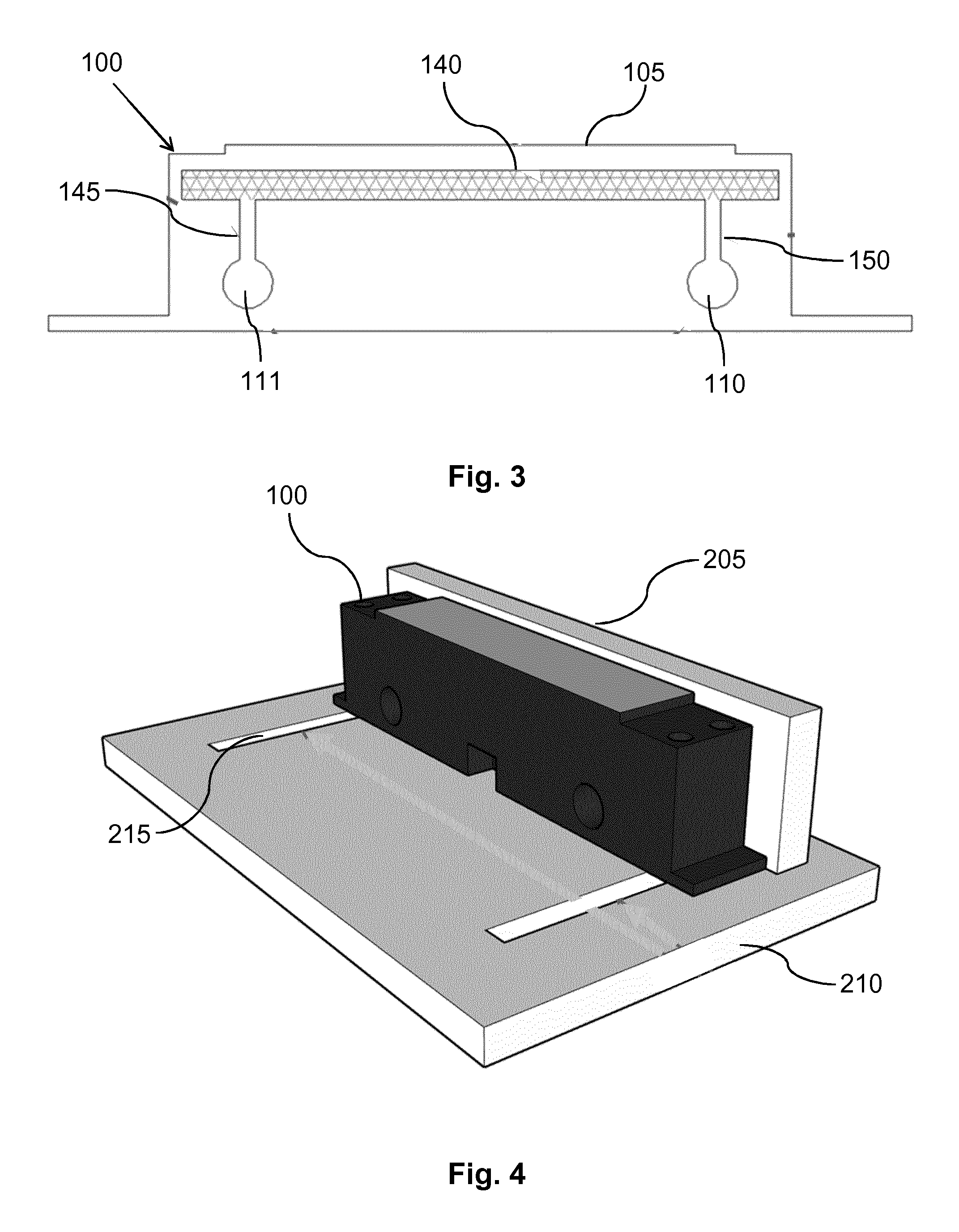
[0063]FIG. 1 shows a first perspective view of an embodiment of the cooling device. The top surface of the cooling device 100, which shall serve as mounting area 105 for the submounts, can be coated, e.g. with Au. To allow for better positioning of the submounts, this surface can also be structured, e.g. by laser-structuring.

[0064]Next to the mounting area 105 recessed areas are provided where electrically insulating PCBs or DCBs can be mounted. These serve as interface, where on the one side the external electrical lines can be connected, on the other side the bond-wires that connect to a laser arrangement like VCSEL-chips can be affixed to (the recesses shall minimize the height difference that the bond-wires have to bridge between VCSEL-chip and PCB / DCB). The 4 electrical supply through holes 120 in the corners of the recessed areas provide tunnels extending from the top adjacent to the mount...


PUM


Abstract

The invention describes a cooling device (100) for cooling a laser arrangement and a laser system comprising at least two of such cooling devices (100). The invention further describes a method of manufacturing the cooling device (100) and the laser system. The cooling device (100) comprises a mounting area for the laser arrangement, a cooling volume (140) comprising cooling channels being arranged to cool the mounting area (105), a coolant inlet and a coolant outlet (150,145) being connected to the cooling channels of the cooling volume (140), a first coolant supply through hole (110) being connected to the coolant inlet (150), a second coolant supply through hole (111) being connected to the coolant outlet (145). The cooling device (100) further comprises at least one coupling element (115, 130, 135) enabling a detachable interconnection to a second cooling device (100) such that upon interconnecting the cooling device (100) to the second cooling device (100), the first coolant supply through hole (110) of the cooling device (100) being connected to a first coolant supply through hole of the second cooling device (100) and the second coolant supply through hole (111) of the cooling device (100) being connected to a second coolant supply through hole of the second cooling device (100), wherein the cooling device (100) being arranged in a way that a coolant can be supplied to the cooling volume via the first coolant supply through hole (110) and the second coolant supply through hole (111). The cooling device (100) enables a cost effective and scalable laser system.

Description

CROSS-REFERENCE TO PRIOR APPLICATIONS[0001]This application is the U.S. National Phase application under 35 U.S.C. §371 of International Application No. PCT / EP2014 / 058828, filed on Apr. 30, 2014, which claims the benefit of European Patent Application No. EP13166176.1, filed on May 2, 2013. These applications are hereby incorporated by reference herein.FIELD OF THE INVENTION[0002]The invention relates to a cooling device for cooling a laser arrangement and a laser system comprising such cooling devices. The invention further relates to methods of manufacturing the cooling device and a laser system comprising such cooling devices.BACKGROUND OF THE INVENTION[0003]U.S. Pat. No. 6,014,312 discloses a cooler for use as a heat sink for electrical components or circuits consisting of several cooler layers which are joined flat to one another, which are stacked on top of one another, which form between channels through which coolant flows and which each discharge into at least one first col...

Claims


Application Information

Patent Timeline
Patent Type & Authority Patents(United States)
IPC IPC(8): H01S3/04H01L23/473H01S5/42F28F7/02F28F9/26H01S5/024H01S5/022H01L23/373F28D21/00
CPCH01S5/02423F28F7/02F28F9/26H01L23/473H01S5/02208H01S5/02248H01S5/423F28D2021/0028F28F2275/14H01L23/3735H01L2924/0002H01L2924/00H01S5/02325
Inventor POLLMANN-RETSCH, JENS
Owner TRUMPF PHOTONIC COMPONENTS GMBH
Why Eureka
Try Eureka