Cathode supply for a fuel cell

a fuel cell and cathode technology, applied in the direction of battery/fuel cell control arrangement, propulsion by batteries/cells, electrochemical generators, etc., can solve the problems of low efficiency in a partial load operational range of modules, large and/or comparatively cost-intensive fuel cell systems, turbines and compressors, etc., to reduce the need for installation space, increase the number of applications, and save costs

Active Publication Date: 2019-11-19
VOLKSWAGEN AG +1
View PDF5 Cites 0 Cited by
  • Summary
  • Abstract
  • Description
  • Claims
  • Application Information

AI Technical Summary

Benefits of technology

[0013]Overdimensioning of corresponding new modules to be used and / or already present, in particular, of a turbine and / or a compressor, should be avoided. Furthermore, the fuel cell unit according to the present invention should have a comparatively high efficiency and be able to operate at a largely optimum operating point comparatively often.
[0015]The cathode supply according to the present invention includes a cathode supply path and a cathode exhaust gas path, at least two fluid pumping devices for pumping a cathode operating medium for the fuel cell being fluido-mechanically coupled into the cathode supply path, and at least one first fluid pumping device of the at least two fluid pumping devices being drivable only on the basis of an enthalpy in a cathode exhaust gas of the fuel cell. The fluid pumping device is used for increasing the fluid pressure of the cathode operating medium and / or for increasing a mass flow rate of the cathode operating medium.
[0016]The first fluid pumping device is drivable exclusively fluido-mechanically by the cathode exhaust gas, since the fuel cell has a certain energy content or a certain enthalpy, recoverable according to the present invention, due to its temperature level and its pressure level in the cathode exhaust gas. In some exemplary embodiments, the fluid pumping device is designed as a compressor, a cathode compressor, a pump, etc. The present invention provides a simple scalability of a fuel cell unit or a fuel cell system.
[0024]According to the present invention, in some exemplary embodiments a reduction of a component size and / or a module size of system components such as, for example, the humidifier and / or the charge air cooler results, and thus a reduction of a necessary installation space for the fuel cell unit. Furthermore, use of standard components or components already available on the market may result, which saves costs. In addition, use of identical parts results in an increase in the number of applications of the corresponding component and again in cost reduction.
[0025]According to the present invention, in some exemplary embodiments an increase in the efficiency of the fuel cell unit results, in particular, in a partial load operational range, due to better layout options of the fuel cell unit, in particular, of the electric turbocharger. A reduction in dynamics of the electric turbocharger is possible and thus a reduction in voltage peaks and / or current peaks in an electrical traction system of the fuel cell system. Accordingly, layout and use of power electronics of the electric turbocharger are also simpler. In addition, increased flexibility results in a fluido-mechanical interconnection of the fuel cell unit.

Problems solved by technology

This entails significant disadvantages for high-powered fuel cell units such as, for example, comparatively large and / or comparatively cost-intensive components, which result in comparatively large and / or comparatively cost-intensive fuel cell systems.
Corresponding modules, in particular, turbines and compressors, are presently not available for such fuel cell units and had to be developed from scratch; such a module has low efficiency in a partial load operational range.
The fuel cell is therefore not operated at a largely optimal operating point.

Method used


Image

  • Cathode supply for a fuel cell
  • Cathode supply for a fuel cell
  • Cathode supply for a fuel cell

Examples


Embodiment Construction

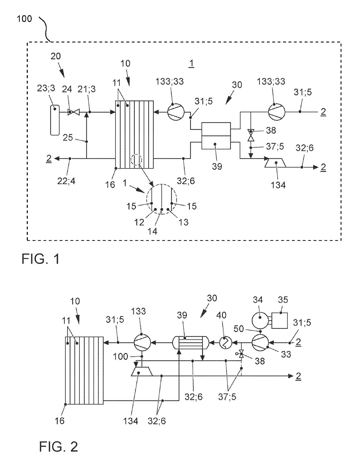
[0034]The present invention is elucidated in greater detail with the aid of five specific embodiments of a cathode supply 30 for a fuel cell 10 of a fuel cell unit 1 for a vehicle (passenger car, passenger transport vehicle, bus, ATV, motorcycle, utility vehicle, (heavy) truck, construction vehicle, construction machine, special vehicle, rail vehicle). However, the present invention is not limited to the exemplary embodiments described below, but is of a fundamental nature, so that it may be applied to other fuel cell units, for example, of a transport system or of another means of transportation, such as an airplane, or also to transportable or stationary fuel cell units. In FIG. 1 the fuel cell unit 1 is for an electric vehicle 100, shown schematically.

[0035]The drawing shows only those sections of fuel cell unit 1 which are needed for understanding the present invention. In particular, an illustration of a periphery of fuel cell unit 1, of sensors, electronic, electrical and powe...


PUM

PropertyMeasurementUnit
pressureaaaaaaaaaa
poweraaaaaaaaaa
powersaaaaaaaaaa

Abstract

A cathode supply (30) for a fuel cell (10) of a fuel cell unit (1) for a fuel cell system is provided, the cathode supply (30) including a cathode supply path (31) and a cathode exhaust gas path (32) and at least two fluid pumping devices (33, 133) for pumping a cathode operating medium (5) for the fuel cell (10) are fluido-mechanically coupled into the cathode supply path (31), at least one first fluid pumping device (133) of the at least two fluid pumping devices (33, 133) being drivable only on the basis of an enthalpy in a cathode exhaust gas (6) of the fuel cell (10). A fuel cell unit for a vehicle, in particular, an electric vehicle, a fuel cell system for a vehicle, in particular, an electric vehicle, or a vehicle in particular an electric vehicle, the fuel cell unit, the fuel cell system, or the vehicle including a cathode supply (30) is provided.

Description

[0001]This claims the benefit of German Patent Application DE102015221597.0, filed Nov. 4, 2015 and hereby incorporated by reference herein.[0002]The present invention relates to a cathode supply for a fuel cell of a fuel cell unit for a fuel cell system. Furthermore, the present invention relates to a fuel cell unit for a vehicle, a fuel cell system for a vehicle, and / or a vehicle, in particular, an electric vehicle.BACKGROUND[0003]A fuel cell of a fuel cell unit of a fuel cell system uses electrochemical conversion of a hydrogen-containing (H, H2) fuel to water, using oxygen (0, 02) to generate electrical energy. For this purpose, the fuel cell contains at least one so-called membrane electrode assembly (MEA) as a core component, which is a structure of an ion-conducting, or proton-conducting membrane and electrodes situated on both sides of the membrane, an anode electrode, and a cathode electrode. In addition, gas diffusion layers (GDL) may be situated on both sides of the membr...

Claims


Application Information

Patent Timeline
Patent Type & Authority Patents(United States)
IPC IPC(8): H01M8/04H01M8/04082H01M8/04089H01M8/04111H01M8/04119B60L50/72B60L58/32
CPCB60L58/32H01M8/04201B60L50/72H01M8/04134H01M8/04111H01M8/04089H01M8/04141H01M2250/20Y02T90/32Y02T90/34Y02T90/40Y02E60/50
Inventor GRUNDEI, DANIELSCHLITZBERGER, CHRISTIANLUCAS, CHRISTIANSCHOLZ, HANNESBRINKMEIER, JAN-PHILIPP
Owner VOLKSWAGEN AG
Why Eureka
Try Eureka