Wing span type self-adapting blade structure
A blade structure, self-adaptive technology, applied in the direction of reducing greenhouse gases, climate sustainability, wind turbines, etc., to achieve the effect of improving the quality of wind power, simple structure, and novel structure
- Summary
- Abstract
- Description
- Claims
- Application Information
AI Technical Summary
Problems solved by technology
Method used
Image
Examples
Embodiment 1
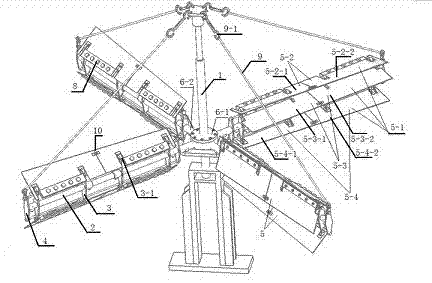
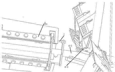
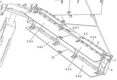
[0092] Embodiment 1: It includes a main shaft 1 , a support rod 2 , two blade supports 3 , two auxiliary supports 4 , two limit rods 7 , two counterweight modules 8 and blade groups 5 . The blade group includes an upper blade 5-2 and a lower blade 5-4. The support rod 2 is connected to the main shaft 1 through a connecting device 6 . An auxiliary bracket 4, two blade brackets 3, and an auxiliary bracket 4 are successively installed on the support rod 2 from the root to the tip. Among the blade bracket 3 and the auxiliary bracket 4, any two brackets are parallel to each other. The limit bar 7 passes through all the blade supports 3 and the auxiliary supports 4 and is parallel to the support bar 2 . One of the limit rods 7 is above the support rod 2 and works with the upper blade 5-2; the other limit rod 7 is below the support rod 2 and cooperates with the lower blade 5-4 to work. The blade 5 - 1 rotates with the rotation axis 3 - 1 on the blade bracket 3 as the rotation axis...
Embodiment 2
[0101] Embodiment 2: on the basis of embodiment 1, carry out further improvement. Increase the support rod 2 from one to three, the three support rods 2 are on the same plane, and the angle between adjacent support rods 2 is 120 degrees. Four blade supports 3, two auxiliary supports 4, and two limit rods 7 are housed on each support rod. An auxiliary bracket 4, four blade brackets 3, and an auxiliary bracket 4 are installed in sequence from the root of the support rod 2 to the tip. Two limit rods 7 respectively pass through all the above-mentioned blade supports 3 and auxiliary supports 4 , and the two limit rods 7 are respectively located at the upper and lower ends of the support rod 2 . On the rotating shaft 3-1 of the blade support 3 on the same support rod 2, a piece of upper floor blade 5-2, a piece of middle floor blade 5-3, and a piece of lower floor blade 5-4 are installed. The upper blade 5-2 is divided into an upper blade A5-2-1 and an upper blade B5-2-2, and the ...
Embodiment 3
[0103] Embodiment 3: on the basis of embodiment 2, carry out further improvement. Increase the support rods 2 from three to four, or five, or six. The number and arrangement of the blade support 3 on each support bar 2, the auxiliary support 4, the stop bar 7, the middle blade 5-3, the upper blade 5-2, and the lower blade 5-4 are the same as those in Implementation 2. This technical solution is more suitable for wind farms with lower wind speeds. It can be started with three-level wind, and can even be erected on the top of urban buildings.
PUM
 Abstract
Description
Claims
Application Information
 - R&D
- Intellectual Property
- Life Sciences
- Materials
- Tech Scout
- Unparalleled Data Quality
- Higher Quality Content
- 60% Fewer Hallucinations
Browse by: Latest US Patents, China's latest patents, Technical Efficacy Thesaurus, Application Domain, Technology Topic, Popular Technical Reports.
© 2025 PatSnap. All rights reserved.Legal|Privacy policy|Modern Slavery Act Transparency Statement|Sitemap|About US| Contact US: help@patsnap.com


