
Blasting vibration predicting method

A prediction method and blasting vibration technology, applied in blasting, measuring devices, geophysical measurements, etc., can solve the problems of not being able to know the blasting vibration frequency and blasting duration, and the analysis and evaluation of blasting vibration is not comprehensive enough, so as to optimize and adjust the blasting design , improve the accuracy and reliability, and improve the efficiency of vibration measurement

Active Publication Date: 2011-07-27
RAILWAY ENG RES INST CHINA ACADEMY OF RAILWAY SCI +1
View PDF5 Cites 32 Cited by
  • Summary
  • Abstract
  • Description
  • Claims
  • Application Information

AI Technical Summary

Problems solved by technology

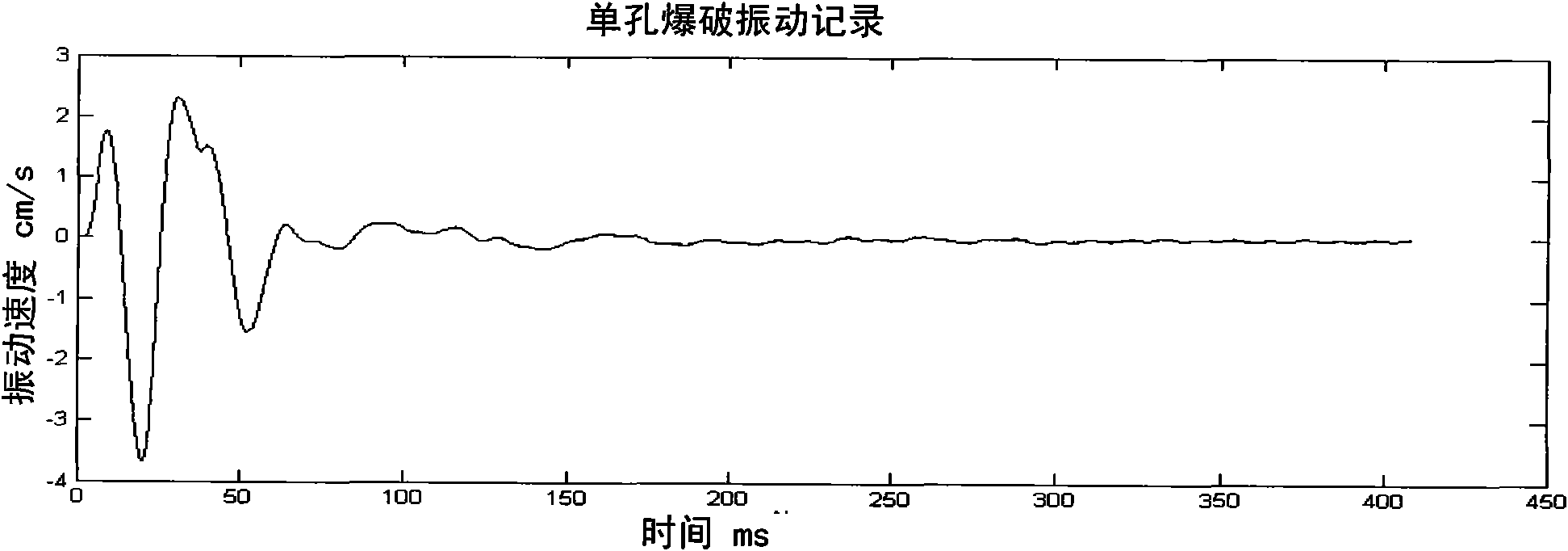
However, the above formula only provides a prediction method for the peak value V of particle vibration velocity, and cannot know the blasting vibration frequency and blasting duration, so the analysis and evaluation of blasting vibration using the above formula is not comprehensive enough

Method used


Image

  • Blasting vibration predicting method
  • Blasting vibration predicting method
  • Blasting vibration predicting method

Examples


Embodiment Construction

[0040] The technical solution of the present invention will be described in further detail below in conjunction with the accompanying drawings and specific embodiments.

[0041] The blasting vibration prediction method provided by the present invention is carried out according to the following steps, see Figure 5 The schematic diagram of the implementation shown:

[0042] First, the position of the reference blast hole 200 and the charge amount of the hole 200 are determined near the blast area 100 . The location of the reference blast hole 200 should be selected as close as possible to the blast area 100 under the premise of ensuring that the blasting of the hole 200 will not affect the blast holes in the blast area 100 .

[0043] Second, at the location coordinates (u 0 , v 0 , r 0 ) to select at least one reference vibration measurement point on the line between the predicted target point 300 and the above-mentioned reference blast hole 200, for example Figure 5 The ...


PUM


Abstract

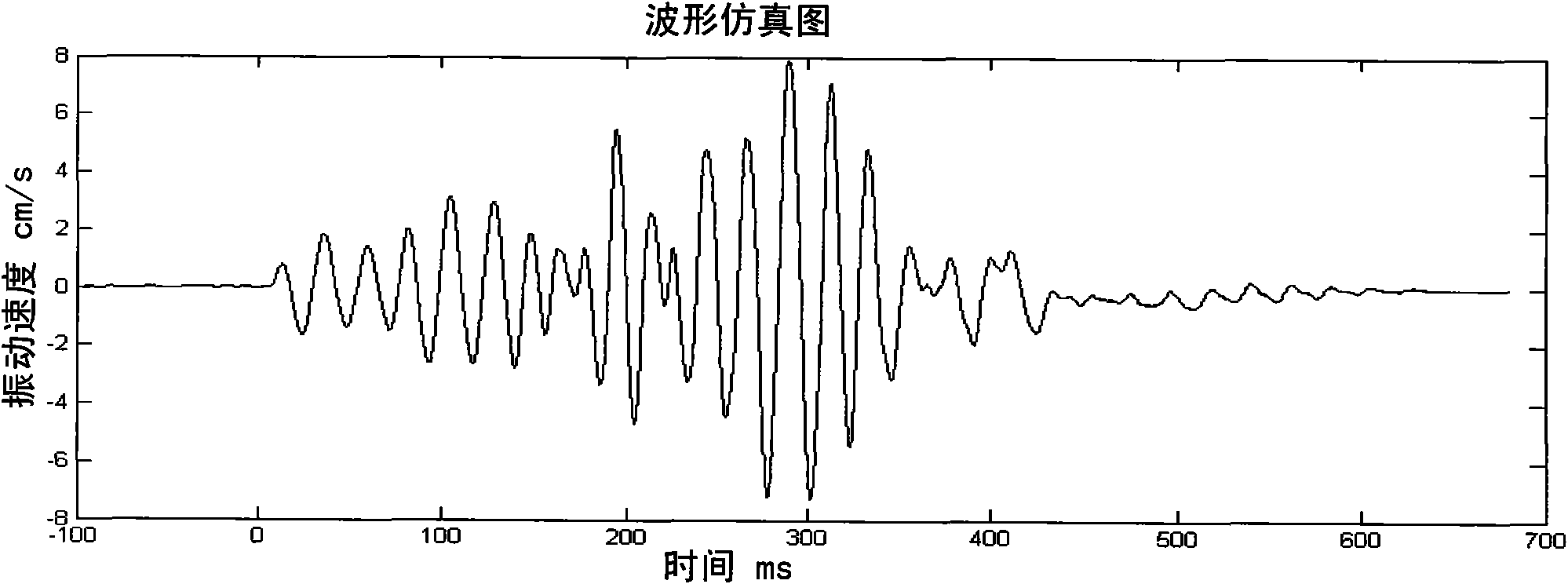
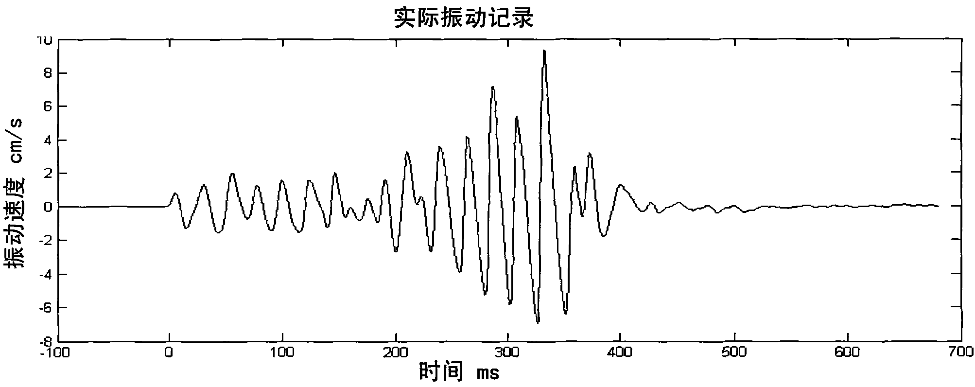
The invention provides a blasting vibration predicting method, which comprises the following steps of: firstly, determining a reference blasting hole and a plurality of vibration measuring points, and placing vibration meters on each vibration measuring point; blasting the reference blasting hole to obtain blasting vibration waveforms having different distance points; and finally, executing a blasting vibration waveform predicting process. In the prediction process, actual blasting vibration test data is obtained firstly, the blasting vibration waveforms and migration stacked delay time of each blast hole on a predicting target point are then calculated according to distance from the predicting target point to the each blast hole and the reference blasting hole, and the vibration waveform of the predicting target point can be obtained based on a vibration wave stacking principle. A blasting vibration predicting result which is obtained by adoption of the method really shows an influence of a topographic condition of a field on blasting vibration, and the integral vibration waveform of the predicting target point can be obtained; a predicted vibration velocity peak value of waveform particles is quite approximate to an actually-measured vibration velocity peak value, and a time difference between the predicted vibration velocity peak value and the actually-measured vibration velocity peak value is also quite small; and an analysis result is accurate and reliable, so that adjustment of a blasting scheme can be better guided.

Description

technical field [0001] The invention relates to the field of blasting vibration safety, in particular to a blasting vibration prediction method capable of predicting blasting vibration waveforms at target points before blasting. Background technique [0002] With the rapid development of my country's infrastructure and mining, blasting, as a necessary means of soil and rock excavation, faces an increasingly complex environment. How to adopt scientific and effective measures to ensure blasting safety to the greatest extent and minimize the impact of blasting vibration on The impact of the surrounding environment has become an urgent task for the smooth implementation of blasting construction and the construction of a harmonious society. Therefore, the evaluation and analysis of blasting vibration has become a problem that people pay more and more attention to. [0003] Currently, the Sadowski formula is usually used Predictive evaluation of blasting vibration effects. In t...

Claims


Application Information

Patent Timeline
IPC IPC(8): G01H17/00G01V1/00F42D1/00
Inventor 杨年华颜景龙张乐郭尧孟海利薛里
Owner RAILWAY ENG RES INST CHINA ACADEMY OF RAILWAY SCI
Learn More