
Built-in antenna

A technology of built-in antenna and dipole antenna, which is applied in the direction of antenna support/installation device, radiating element structure, etc. It can solve the problems of poor signal performance, uncertainty and lack of direction diagram of built-in antenna, etc., and achieve good determination performance and improve signal performance

Inactive Publication Date: 2011-07-27
HUAWEI DEVICE CO LTD
View PDF4 Cites 1 Cited by
  • Summary
  • Abstract
  • Description
  • Claims
  • Application Information

AI Technical Summary

Problems solved by technology

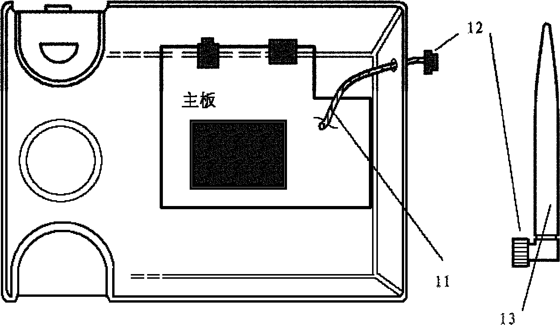
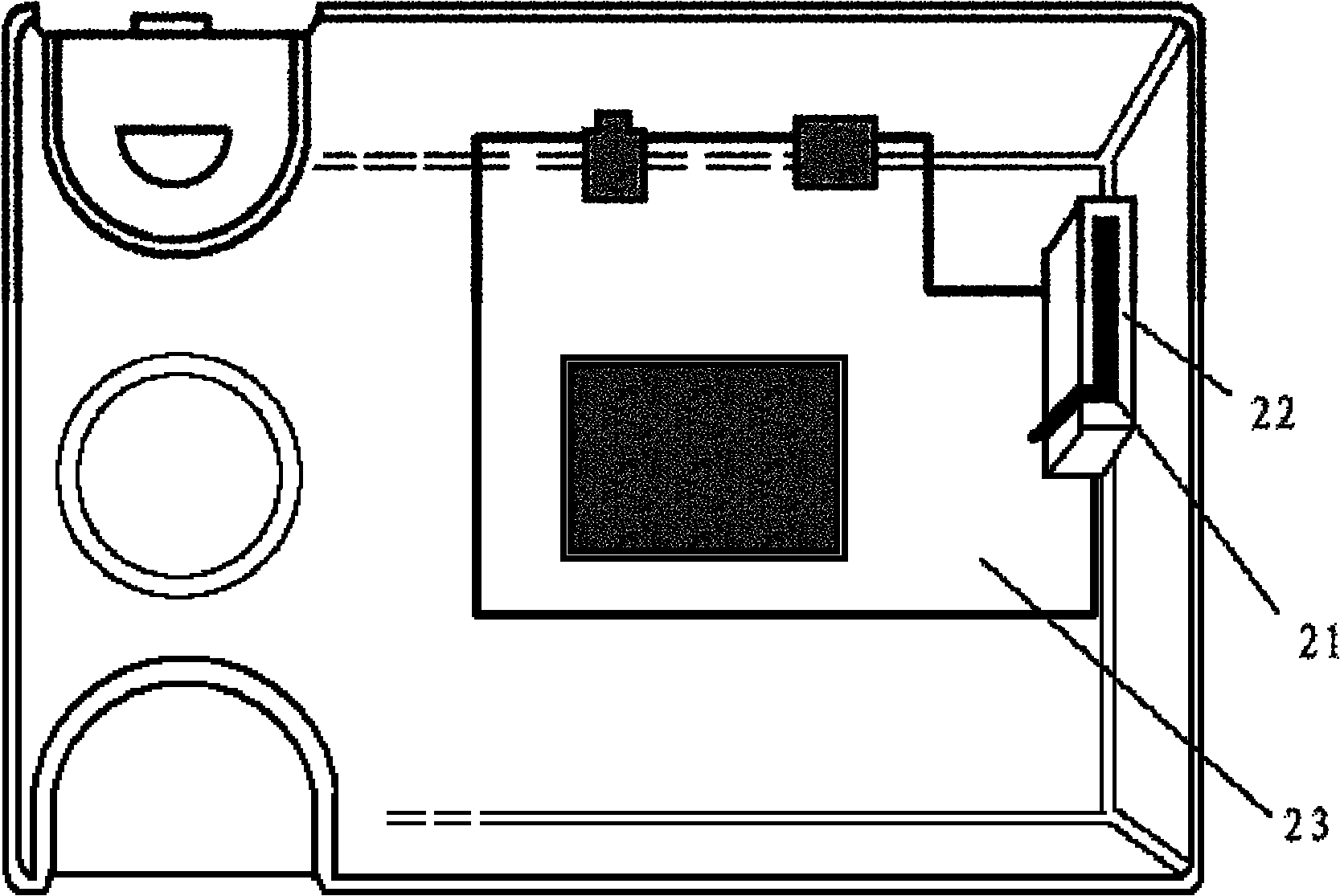
[0004] In the process of using the above-mentioned built-in antenna, the inventor found that there are at least the following problems in the prior art: figure 1 As far as the external antenna is concerned, since the outer conductor of the RF line connected to the external antenna is directly grounded, and figure 2 The built-in antenna lacks the grounding outer conductor, but the function similar to grounding is completed through the main board, resulting in the uncertainty of the pattern of the built-in antenna, resulting in poor signal performance; in addition, due to figure 2 The built-in antenna is a monopole antenna, and the far end of the monopole antenna needs to be far away from the ground, so that the figure 2 When the device placement method in the method cannot ensure that the far end of the monopole antenna is far away from the ground, it will also cause uncertainty in the pattern of the built-in antenna, resulting in poor signal performance

Method used


Image

  • Built-in antenna
  • Built-in antenna
  • Built-in antenna

Examples


Embodiment Construction

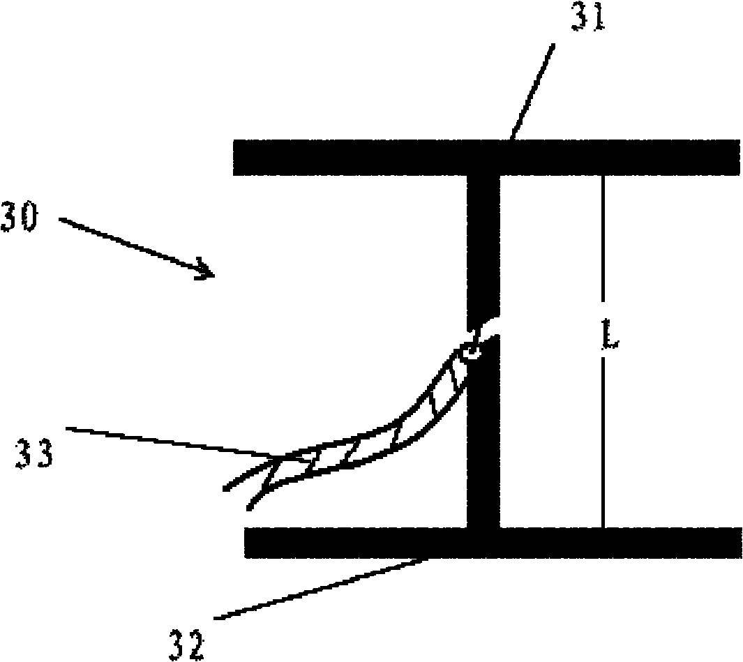
[0022] An embodiment of the present invention provides a built-in antenna, including a dipole antenna and a radio frequency wire. Specifically, the dipole antenna includes two dipoles arranged along the inner wall of the terminal housing; the inner conductor at one end of the radio frequency wire Connected to the radio frequency channel, the outer conductor is grounded; the inner conductor at the other end of the radio frequency line is connected to one vibrator of the dipole antenna, and the outer conductor at the other end of the radio frequency line is connected to the other vibrator of the dipole antenna.

[0023] The built-in antenna is realized by the above method, and since a dipole antenna can be formed, both the inner and outer conductors of the radio frequency line can be connected to the antenna, and there is no lack of a grounded outer conductor like the prior art, so that the directional diagram of the built-in antenna has a unique Better determinism, improved sign...


PUM


Abstract

The embodiment of the invention discloses a built-in antenna, relates to the technical field of wireless communication, and solves the problem of poor signal performance of the built-in antenna. The built-in antenna provided by the embodiment of the invention comprises a dipole antenna and a radio frequency wire, wherein the dipole antenna comprises two vibrators which are arranged along the inside wall of a terminal shell; an inner conductor at one end of the radio frequency wire is connected to a radio frequency channel and an outer conductor is grounded; the inner conductor at the other end of the radio frequency wire is connected to one vibrator of the dipole antenna; and the outer conductor at the other end of the radio frequency wire is connected to the other vibrator of the dipole antenna. The built-in antenna provided by the embodiment of the invention can be used in various types of terminal equipment, and is used in fixed stations in normal situations.

Description

technical field [0001] The invention relates to the technical field of wireless communication, in particular to a built-in antenna used in the wireless communication technology. Background technique [0002] In wireless communication technology, antennas are needed to transmit and receive signals, and current antennas are roughly divided into external antennas and internal antennas. The structure of the external antenna is as follows figure 1 As shown, the radio frequency line 11 connected to the radio frequency path on the motherboard is extended to the outside of the case, and then connected to the external antenna 13 with a matching connector 12 . Since the external antenna 13 needs to occupy a lot of external space, and needs to be equipped with accessories such as the radio frequency cable 11, the connector 12, and the external antenna 13, it will increase the cost and affect the appearance; therefore, the internal antenna has become a more commonly used antenna. [0...

Claims


Application Information

Patent Timeline
Patent Type & Authority Applications(China)
IPC IPC(8): H01Q1/22H01Q1/36
Inventor 张学飞陈洪艳曾昭才陈绍清
Owner HUAWEI DEVICE CO LTD
Learn More