A technique according to the invention provides for transmitting identification, location, and
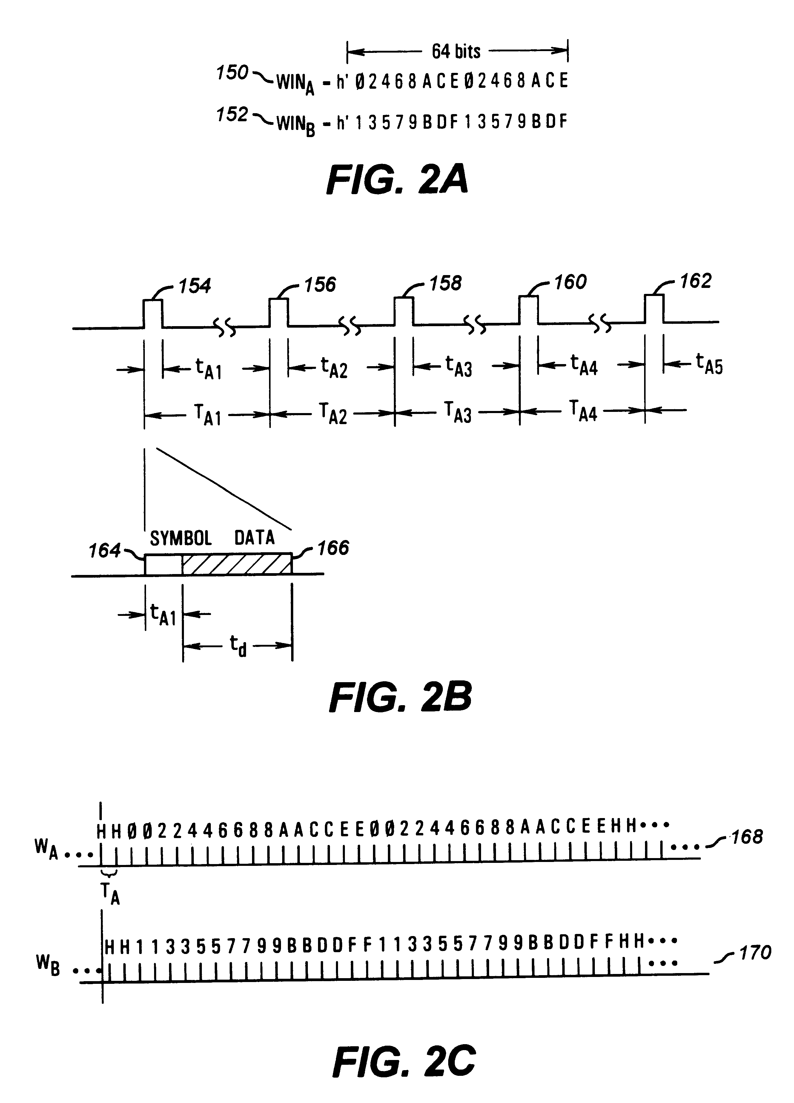
telemetry data while conserving power and increasing available bandwidth. According to the invention, each transmitter identification is split into multiple, smaller, timed transmission packets. The transmitter then transmits a portion of that identification (such as a single bit) periodically, such as once per second. The period of time between transmissions is precise, such that once the system identifies a transmitter, it can then accurately identify the transmitter based upon the next transmission packet's
time of arrival. Because of the small bandwidth occupied by and the limited energy used in each single transmission bot the individual transmissions and resulting identifications are resistant to collisions from other transmitters, as well as from
noise.
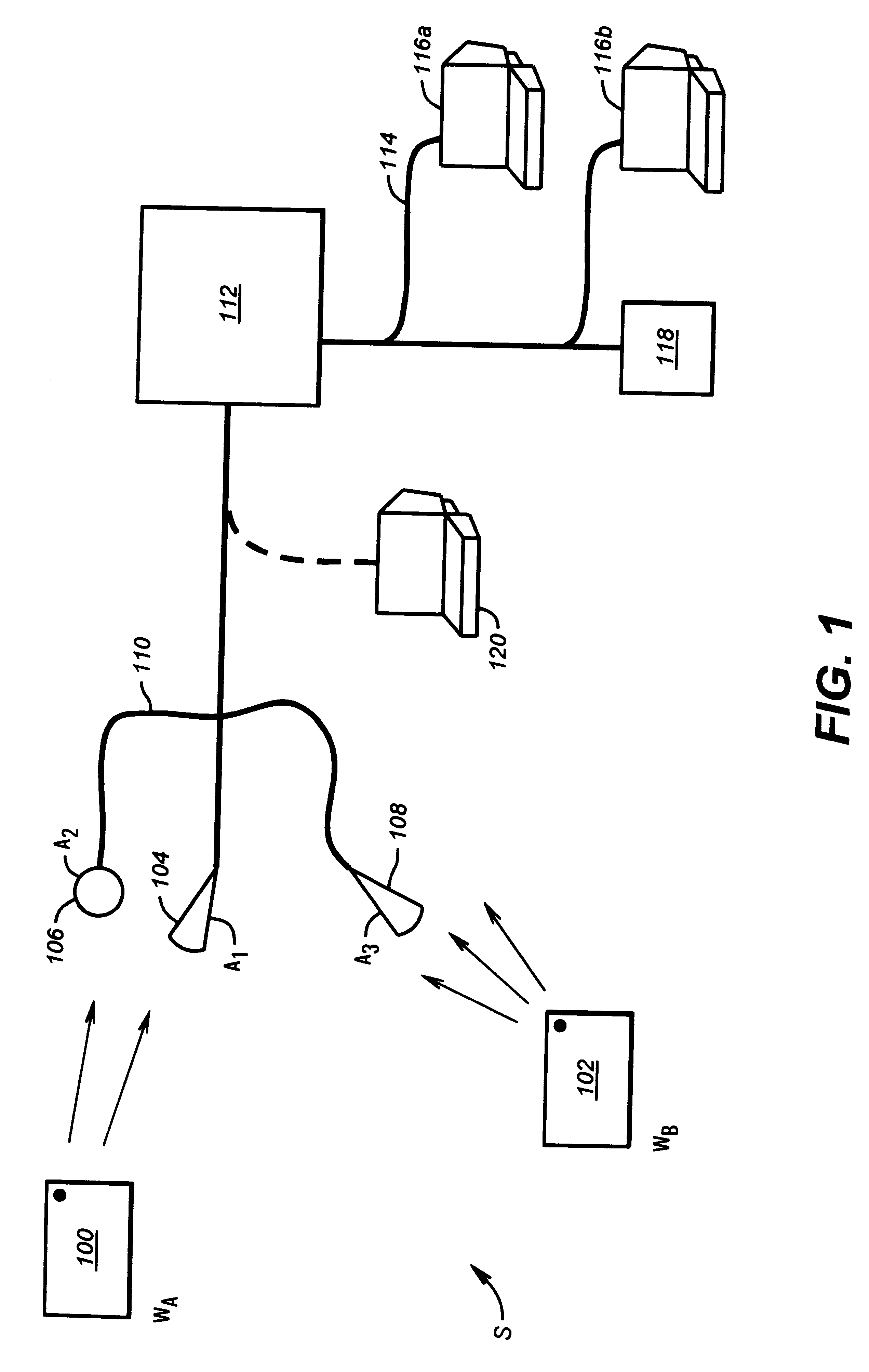
A
signal processor, (currently, a
server over an RS-485
bus) receives such packets from all receivers, recognizes identifications from previously "unacquired" transmitters, and maintains information on previously acquired transmitters. From the start of receiving transmissions (or "symbols") that are unexpected or unscheduled, the
signal processor establishes an interval from the periodicity of the transmitted symbols. The signal processor attempts to lock onto a transmitter that was newly introduced into the field of the
receiver based on the transmission interval. The signal processor does so by correlating the unexpected and unscheduled symbols and calculates a transmission period, or interval. It then predicts times to expect future symbols. As future symbols are received, their additional identification information is accumulated into the system, which both reinforces the
algorithm's assurance that future receptions are from a given transmitter and more positively identifies that transmitter. Though the average
delay between symbols may vary randomly somewhat or drift, the
repeatability of symbols each second (i.e.,
jitter) is highly accurate. This
repeatability allows the system to identify, and infer with an increasingly higher
degree of certainty, the presence of a particular transmitter based on its transmission's
time of arrival at the
receiver.
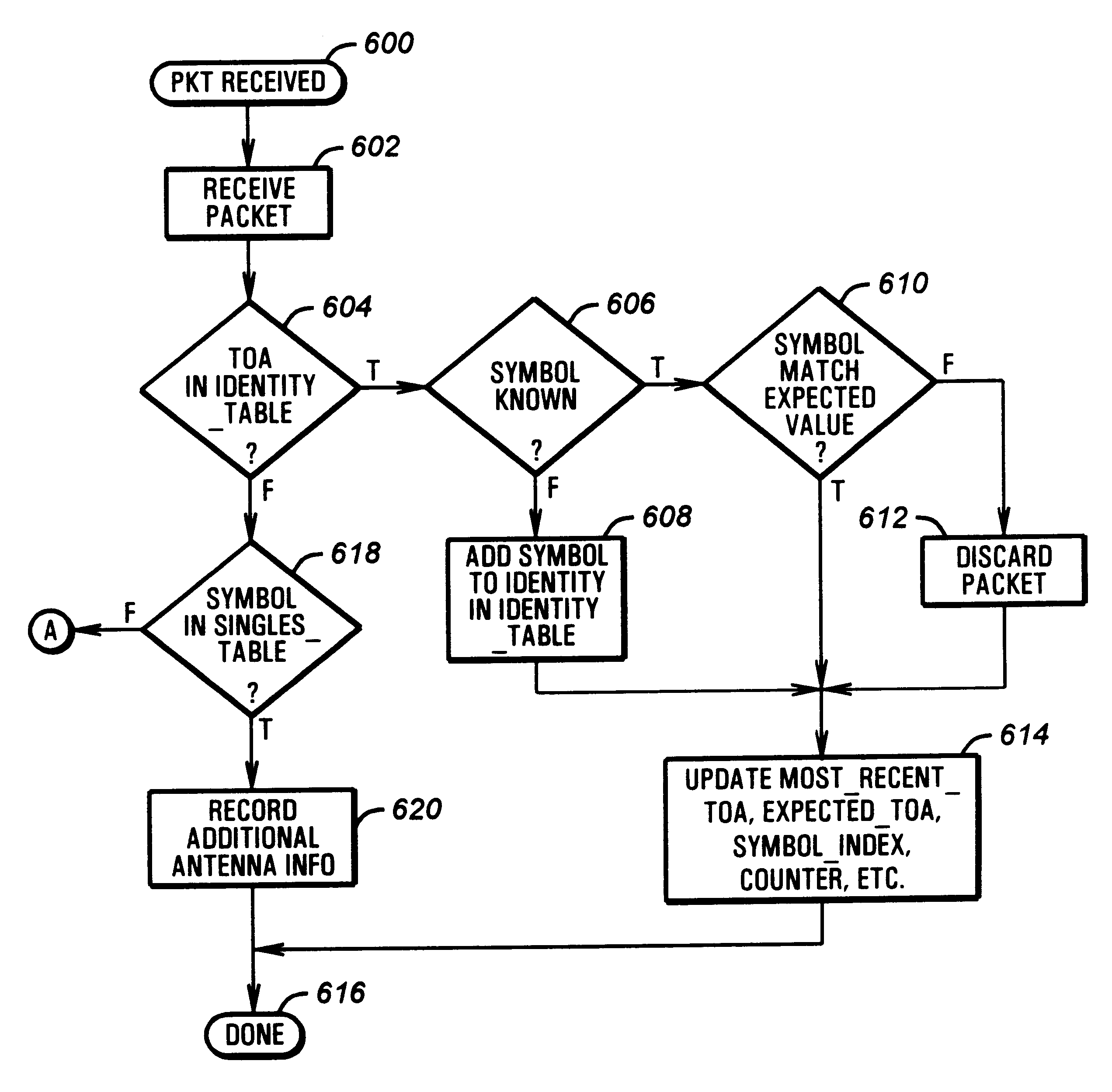
When an unexpected symbol is first received, the system holds that uncorrelated symbol in a
queue, and waits for the transmission of subsequent, associated symbols to establish an interval. Once that interval is established, the signal processor accumulates subsequent transmissions to establish the transmitter's identity. Partial identifications may be used to establish a probable identity. Once associated, approximately or exactly, the signal processor expects subsequent symbols at the predetermined interval. Lack of arrival of expected symbols is tolerated, but with locking lost after a certain number of "missed" symbols. As information packets reflecting subsequent receipts of symbols are detected, the information is added to the identification within the system. If no matching identification appears in the
database, the new transmitter data is then added to the
database. Once all
data bits have been received, the identification of the transmitter is positively known. Successive transmissions of symbols received at known transmission periods allow for tee continuous supervision of the device without the device transmitting the entire identification on every transmission, unnecessarily using the energy and unnecessarily occupying channel space by continuously transmitting that complete identification code.
One
advantage of the technique is that once an interval is acquired, the transmitter can be identified based primarily when it transmits, with the actual transmitted symbol verifying the identity of the transmitter. The transmission of a symbol, however, which is only a portion of the identification code, takes a proportionally low amount of power to transmit. For example, assume a system which transmits an identification code once every second requires some predetermined power to transmit. By dividing the identification code into some number of portions and transmitting only one portion every second or so, the disclosed transmitter could require over an
order of magnitude less power than the prior system, while maintaining the same transmission, and thus tracking, rate. Particularly advantageous is the
immunity of a device's identification to various kinds of noises. A smaller packet containing the "same data" will have a smaller possibility of being lost to
noise. Losing data to
noise is a function of the time that the data occupies the channel. Therefore, the smaller the data packet, for the same amount of data, the greater the
noise immunity. Assume a typical system would take 64 milliseconds to transmit a 64 bit identification packet. Since the disclosed embodiment takes approximately 600 microseconds for each bit, then the
noise immunity of transmitting a single bit, rather than 64 bits is increased over 100 times, providing 20 db more noise immune.
Prior systems could reduce power by transmitting less frequently, but that would
cut down on the ability of the system to supervise the presence of a "TAG", or device, in real time as well as obviating the practical use of an antenna for "finding" the device. Once again, by using the disclosed techniques, the present system has longer life on the same battery, has an abundance of devices that can exist in the same area, provides a high tracking rate, and has greatly increased
immunity to noise.
Noise immunity occurs for all forms of noise, including other like devices' transmissions, other same frequency but dissimilar transmissions, and man-made and more natural
Gaussian, Schott and
impulse noise.

