Method for producing a prefabricated part from an unmachined part by means of a milling tool

A technology for milling cutters and blanks, which is applied in the direction of milling cutters, milling machine equipment, manufacturing tools, etc., can solve the problems of prolonging processing time and prolonging additional paths, and achieve the goals of reducing axial load, protecting cutters, and improving process safety Effect

Active Publication Date: 2011-07-27
开明技术股份公司
View PDF10 Cites 4 Cited by
  • Summary
  • Abstract
  • Description
  • Claims
  • Application Information

AI Technical Summary

Problems solved by technology

Therefore, high-performance milling cutters are usually limited in their insertion behavior to extremely shallow insertion angles, which prolong the additional path for reaching the machining depth and thus the machining time

Method used


Image

  • Method for producing a prefabricated part from an unmachined part by means of a milling tool
  • Method for producing a prefabricated part from an unmachined part by means of a milling tool
  • Method for producing a prefabricated part from an unmachined part by means of a milling tool

Examples


Embodiment Construction

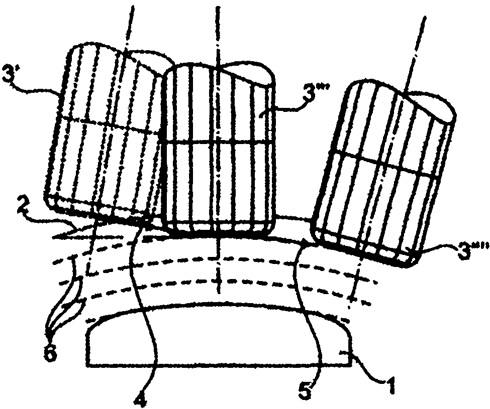
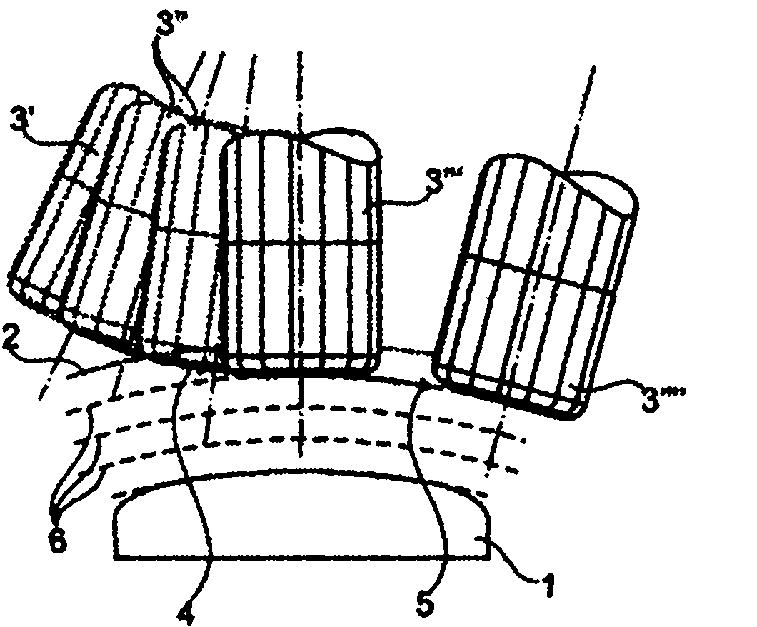
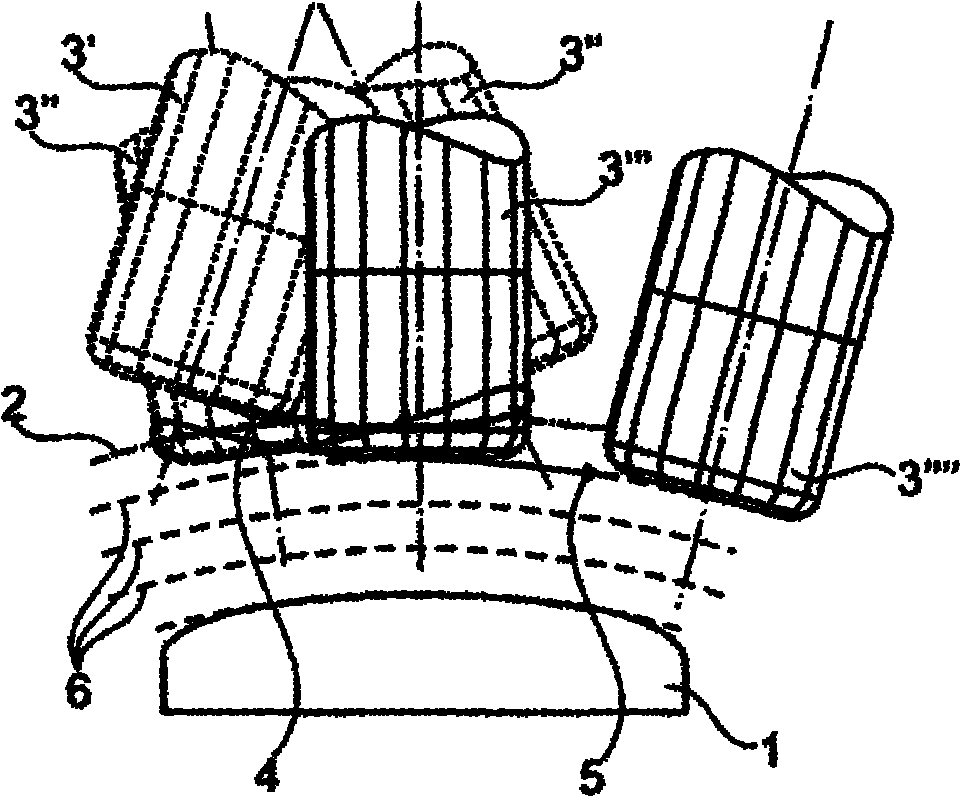
[0031] In the following description of the different embodiments of the method according to the invention for producing a finished part 1 from a blank 2 by means of a milling cutter 3 , corresponding or identical components are each given the same reference numerals.

[0032] In this case, the milling cutter 3' is at the beginning of the insertion path, the milling cutter 3" is during the insertion path, the milling cutter 3"' is at the end of the insertion path or the starting point of the subsequent machining, and the milling cutter 3"" is during the subsequent machining.

[0033] The insertion path of the milling cutter 3, i.e. the tool path during insertion, is marked with the reference numeral 4, while the machining path of the milling cutter 3, i.e. the milling cutter path during machining, is indicated with the reference numeral 5, and the reference numeral 6 indicates the difference in machining. depth of infeed.

[0034] exist Figures 1a to 1c The method according t...


PUM


Abstract

The present invention relates to a method for producing a prefabricated part (1) from an unmachined part (2) by means of a milling tool (3). Said milling tool (3), when plunged into the material of the unmachined part (2), is automatically tilted in the advancing direction and/or laterally to the advancing direction in relation to the immersion path (4) that deviates from the direction (5) of the milling tool (3) that is machined immediately thereafter.

Description

technical field [0001] The invention relates to a method for producing a finished part from a blank by means of a milling cutter. Background technique [0002] As a rule, a special motion guidance of the milling cutter during insertion into the material to be machined is particularly important when the milling cutter has to reach large infeed depths in the axial direction by largely end-face contact. In milling operations with large infeed depths into the material, for example in the case of roughing, different methods are used in practice. As a rule, in a separate operation—generally by means of drilling—material is removed at the starting point so that the starting point of the machining can be reached in the axial direction without removing material. [0003] If the specified insertion point cannot be predetermined or preprocessed, an additional ramp-shaped or helical milling cutter path is calculated starting from the contour of the blank in the direction of the startin...

Claims


Application Information

Patent Timeline
Patent Type & Authority Applications(China)
IPC IPC(8): B23C3/00
CPCB23C3/00Y10T409/303808B23C5/00
Inventor P·布兰布斯E·容J·科赫
Owner 开明技术股份公司
Why Eureka
Try Eureka