Acoustic transducers for underwater navigation and communication

a technology of underwater navigation and communication, applied in direction finders using ultrasonic/sonic/infrasonic waves, mechanical vibration separation, instruments, etc., to achieve the effect of increasing the effective electromechanical coupling coefficien

Active Publication Date: 2014-01-28
BROWN DAVID ALAN +2
View PDF11 Cites 4 Cited by
  • Summary
  • Abstract
  • Description
  • Claims
  • Application Information

AI Technical Summary

Benefits of technology

[0011]In another embodiment, two omnidirectional reference sources are used, one positioned equally above and one below the source producing the spiral wavefront, to enable the estimation of the vertical bearing angle of an incoming signal by measuring the phase difference. Said two omnidirectional reference sources can also improve the horizontal bearing angle estimation as the summation of the pair will have an acoustic center collocated with the source producing the spiral wavefront. in this embodiment a preferred burst sequence of acoustic pulses would be: omni-reference 1, a time delay, omni-reference 2, a time delay, and spiral wavefront signal. The phase difference between omni-reference 1 and omni-reference 2 signals can be processed to yield a vertical (depression) angle. Further, for a spiral source positioned between the two omni-reference sources, the horizontal bearing estimation derived from phase measurements can take into account the phase due to the vertical offset from the horizontal plane to improve bearing angle estimation accuracy.
[0014]According to another aspect of the present invention, radially polarized cylindrical piezoelectric elements having a height to diameter aspect ratio less than unity may be utilized to increase the effective electromechanical coupling coefficient and useable power factor bandwidth when producing circumferential vibrations. Alternatively radially polarized cylindrical piezoelectric elements having a height to diameter aspect ratio greater than about unity may be utilized to increase the effective electromechanical coupling coefficient and useable power factor bandwidth when vibrating at higher frequency upper-branches inducing axial and circumferential vibrations. In this variant, the omnidirectional reference signal can be produced at or near the vicinity of the frequency of the electromechanical resonance mode corresponding to the first axial resonance or “upper-branch” of the cylindrical transduction element and in a preferred embodiment the resonance frequency of this upper-branch mode is nominally the same as the frequency of the resonance of the acoustic dipole modes of the spiral wavefront on a separate transducer. This variant has the advantage that the frequency response, and in particular the phase response, will be more closely matched over a wider frequency range.
[0015]Another object of the preferred embodiment of the invention is to substantially mechanically isolate the ends of the hollow cylindrical piezoelectric elements from their cap and base, or from each other when multiple elements are utilized, while maintaining an air backed cavity in order to improve the vibration response of said cylindrical elements. In the preferred embodiment the transducer element is air backed, said elements having a base and a cap that are mechanically detached from the piezoelectric cylinder by means of a compliant spacer.
[0016]Still another aspect of the invention is realized by including an internal cylindrical supporting structure connecting the cap and the base of the transducer in order to increase the operational depth capabilities of the device and to reduce axial loading on the piezoelectric elements thereby maintaining the ability of the distal ends of the cylindrical elements to freely vibrate.

Problems solved by technology

The challenge is to realize and effective transducer to accomplish this goal.

Method used


Image

  • Acoustic transducers for underwater navigation and communication
  • Acoustic transducers for underwater navigation and communication
  • Acoustic transducers for underwater navigation and communication

Examples


Embodiment Construction

[0044]The present invention now will be described more fully hereinafter with reference to the accompanying drawings and mathematics to fully convey the scope of the invention to those skilled in the art.

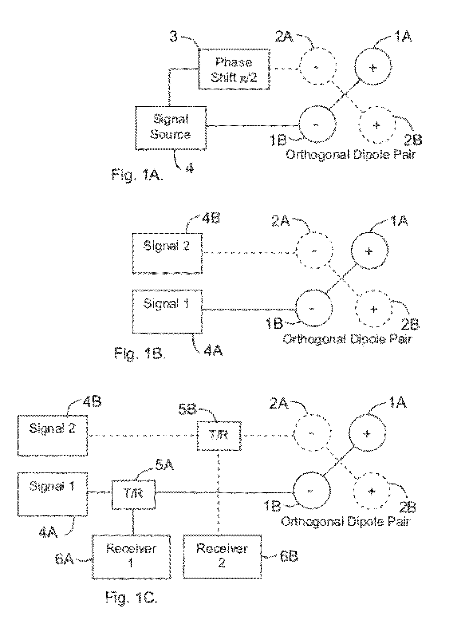
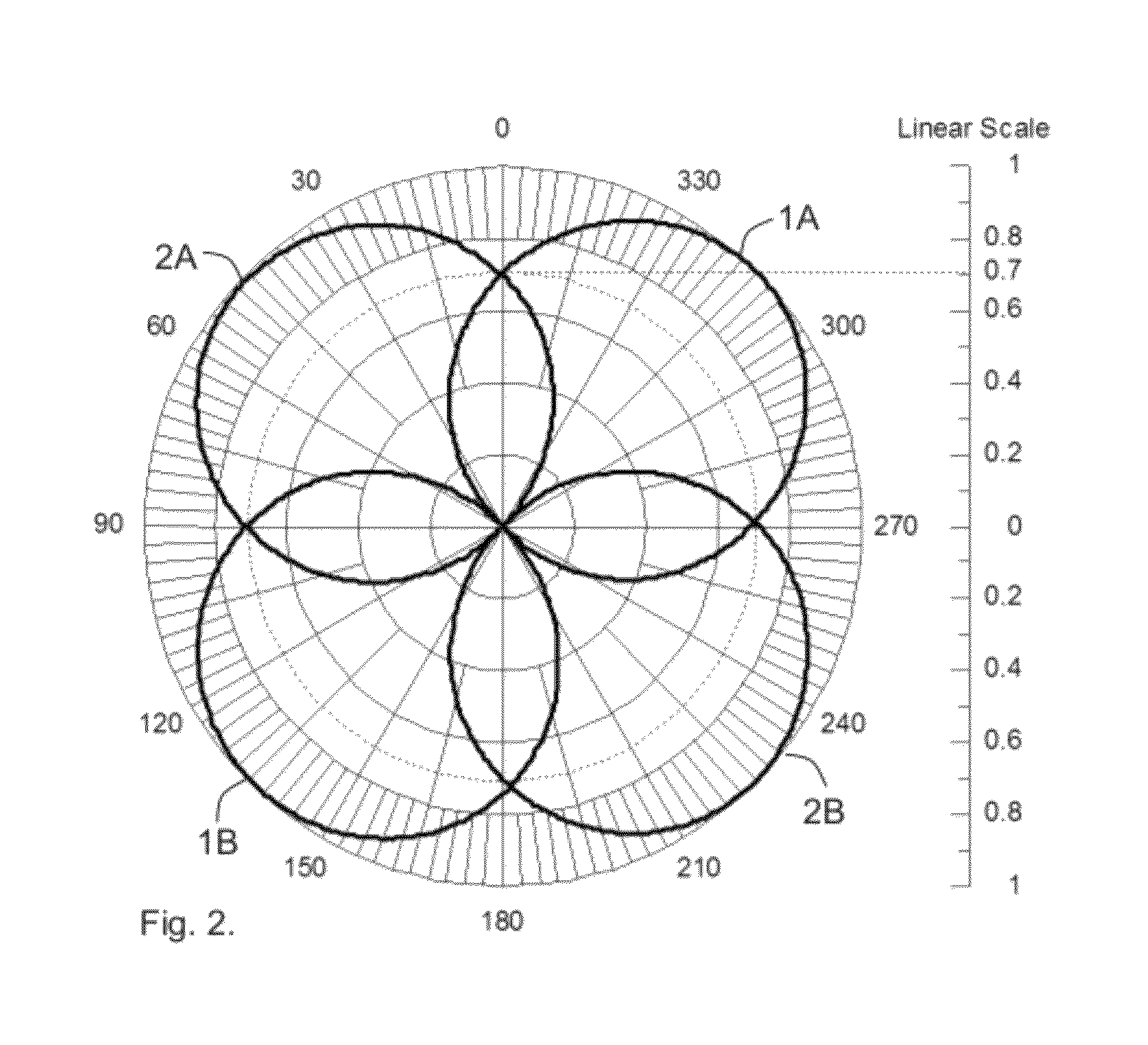
[0045]FIG. 1 is a schematic illustration of two acoustic doublet or dipole transducers each consisting of two individual transducer elements. It is widely known to those skilled in the art that when the elements are spaced on the order or less than a half acoustic wavelength and the elements are driven 180 degrees out-of-phase (opposite polarity), the resulting radiation pattern or directional factor is cosinusoidal, H(θ)=cos θ where θ is measured with reference to a line intersecting the acoustic centers of each element. It is widely known that the transmit radiation pattern and receive radiation pattern are the same as guaranteed by reciprocity. Such a pattern itself is generally referred to as an acoustic dipole (pattern) or figure-eight. FIG. 1 also depicts a second pair of tran...


PUM


Abstract

Methods and transducers for producing acoustical signals having a spiral wavefront with omnidirectional magnitude and a phase that varies with angle and transducers for producing broadband omnidirectional reference signals for underwater navigation and communication.

Description

STATEMENT OF GOVERNMENT SUPPORT[0001]This invention was made without government funding.RELATED APPLICATION(S)[0002]None.FIELD OF THE INVENTION[0003]The present invention relates to underwater acoustic transducers and in particular to acoustic sources producing spiral wavefront for underwater navigation to determine bearing angle and for communication.BACKGROUND OF THE INVENTION[0004]Underwater acoustic transducers are used in communications and to aid in determining the position and navigation of submerged objects. One such method to aid in navigation is to transmit a spiral wavefront consisting of a signal having a magnitude that is nominally constant but whose phase varies linearly as a function of azimuthal angle in a defined plane. Such a spiral wavefront signal can be compared with a reference signal of constant phase to determine the bearing angle. A beacon carrying such a transducer producing a spiral wavefront may be employed to transmit signals that can be detected by mult...

Claims


Application Information

Patent Timeline
Patent Type & Authority Patents(United States)
IPC IPC(8): H04B13/02H04B1/02G01S3/80
CPCG10K2200/11B06B1/0637G10K11/008
Inventor BROWN, DAVID ALANARONOV, BORISBACHAND, COREY LIONEL
Owner BROWN DAVID ALAN
Why Eureka
Try Eureka