

Parking brake control device
A technology of braking control and braking device, applied in the direction of automatic starting device, brake, brake actuator, etc., can solve the problems of inability to ensure braking force, inability to release parking brake, inability to release, etc.
- Summary
- Abstract
- Description
- Claims
- Application Information
AI Technical Summary
Problems solved by technology
Method used
Image

Examples
no. 1 example
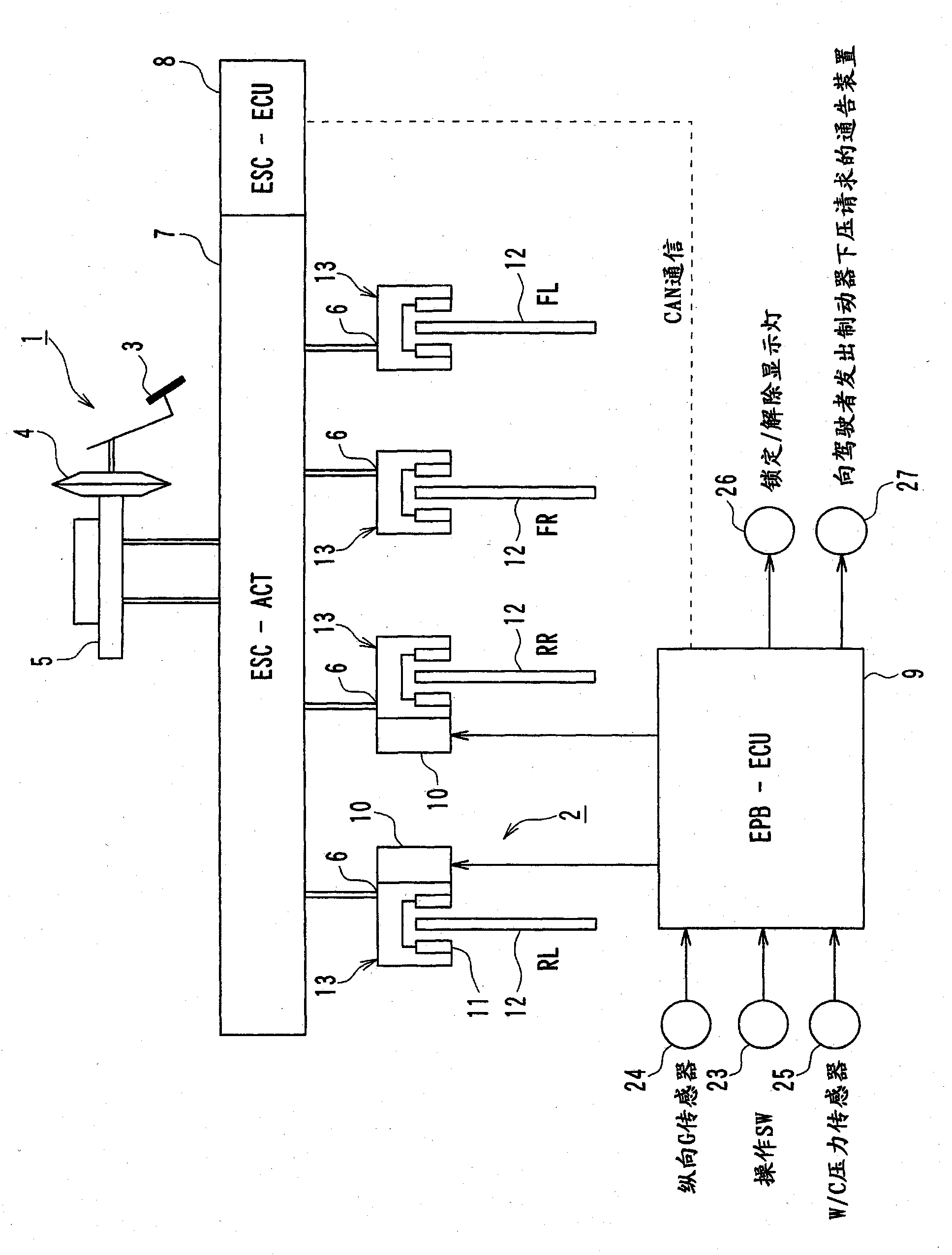
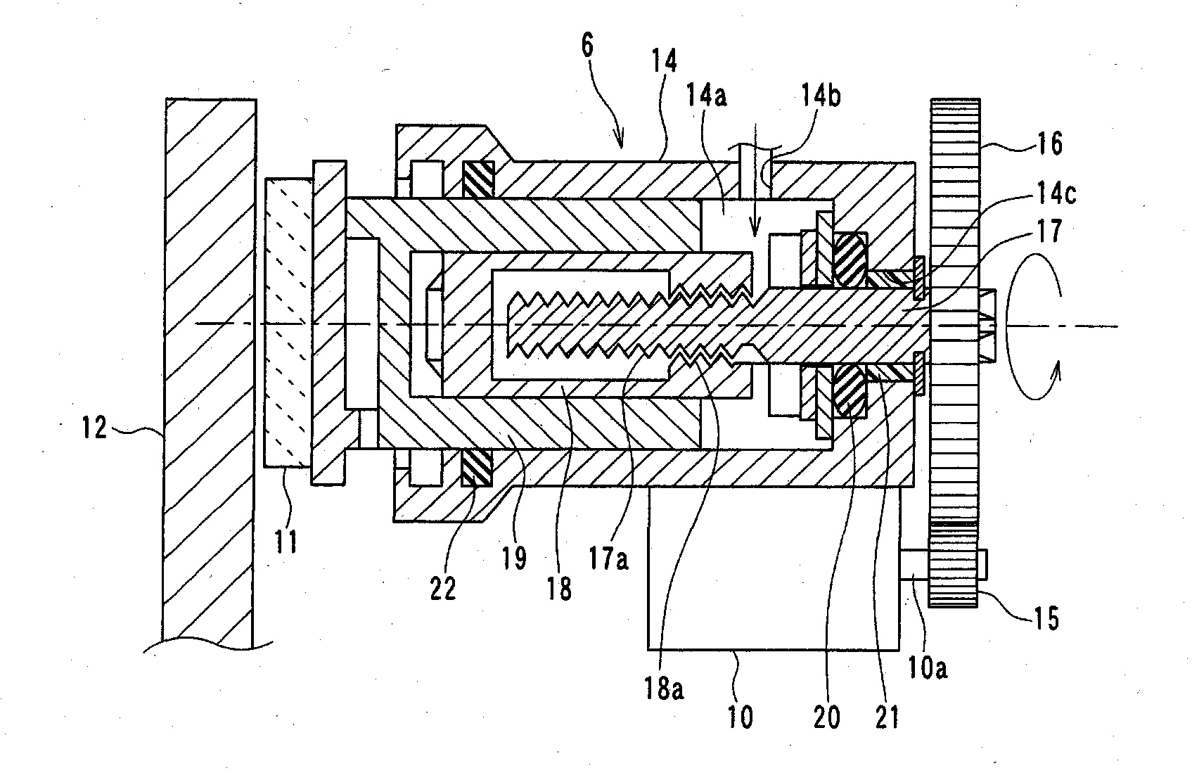
[0037] The first embodiment of the present invention will be described below. This embodiment uses a vehicle brake system as an example in which a disc brake EPB is applied to the rear wheels. figure 1 It is a schematic diagram showing the outline of a vehicle brake system to which the parking brake control device according to the present embodiment is applied. figure 2 It is a schematic cross-sectional view of the rear wheel brake mechanism provided in the brake system. The present embodiment is described below with reference to the drawings.
[0038] Such as figure 1 As shown in the brake system, the brake system is provided with a service brake 1 and EPB 2. The service brake 1 is equivalent to a second braking device that generates braking force based on the driver's pedal force, and EPB 2 is equivalent to restricting the movement of the vehicle when the vehicle is stopped The first braking device.
[0039] For the service brake 1, the servo unit 4 doubles the pedal force corr...
no. 2 example
[0099] Now, the second embodiment of the present invention will be explained. In this embodiment, the lock control and release control are improved from the lock control and release control in the first embodiment. However, other aspects of this embodiment are the same as the first embodiment, so only the differences from the first embodiment will be described below.
[0100] In this embodiment, an improved method of issuing a brake pedal depression request to the driver based on the faulty part of the ESC is used to perform lock control and release control.
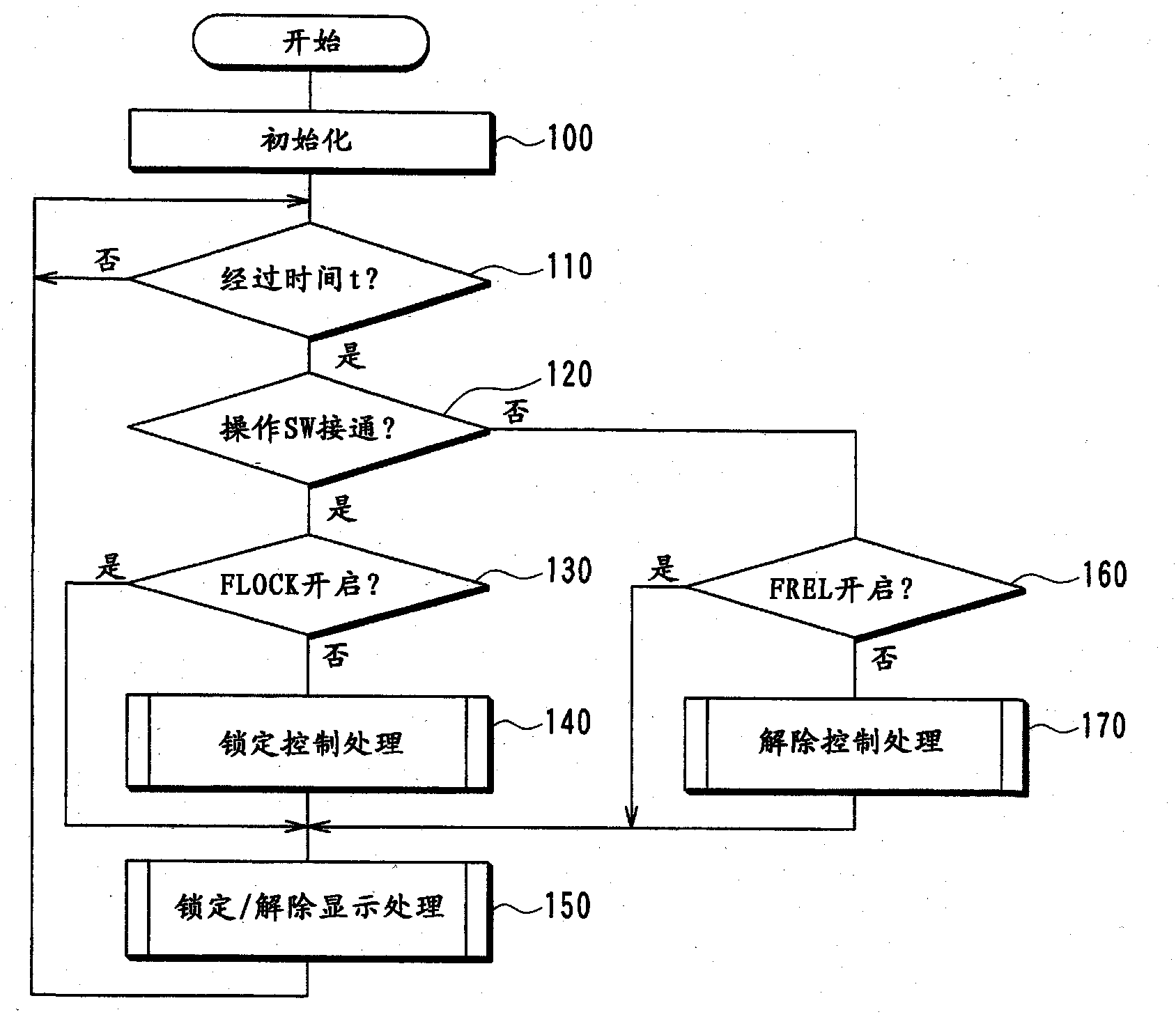
[0101] Picture 12 It is a flowchart showing the details of the lock control processing according to the present embodiment. Such as Picture 12 As shown in, basically, the process is the same as the above Figure 4 The lock control process shown in is the same. However, in step 210a, it is judged whether it is impossible to use the W / C pressurization function of the automatic pressurization function of the actuator 7, inst...
no. 3 example
[0109] Now, the third embodiment of the present invention will be explained. In this embodiment, the lock control and release control are improved from the lock control and release control in the first embodiment. However, other aspects of this embodiment are the same as the first embodiment, so only the differences from the first embodiment will be described below.
[0110] In this embodiment, the lock control and release control are performed by using an improvement in issuing a brake pedal depression request to the driver depending on the required depression amount.
[0111] Figure 14 It is a flowchart showing the details of the lock control processing according to the present embodiment. In this embodiment, as Figure 14 As shown in the above, basically the process is the same as the above Figure 4 The lock control process shown in is the same. However, in steps 220a-220c, the processing when the ESC fails is improved.
[0112] More specifically, if an affirmative determinat...
PUM
 Abstract
Description
Claims
Application Information