
Movable multifunctional collodion cotton mop

A collodion mop, movable technology, applied in the direction of cleaning carpets, cleaning floors, cleaning equipment, etc., can solve the problems that affect the mopping effect, small contact area, limit of collodion size, etc., achieve long service life, simple operation, The effect of extending the service life

Inactive Publication Date: 2011-08-03
张承志
View PDF3 Cites 54 Cited by
  • Summary
  • Abstract
  • Description
  • Claims
  • Application Information

AI Technical Summary

Problems solved by technology

[0005] 3. Due to the limitation of the dehydration method, the collodion can only be oval, and the size of the collodion is also limited, and the contact area with the ground is relatively small, which affects the effect of mopping the floor

Method used


Image

  • Movable multifunctional collodion cotton mop
  • Movable multifunctional collodion cotton mop
  • Movable multifunctional collodion cotton mop

Examples


Embodiment 1

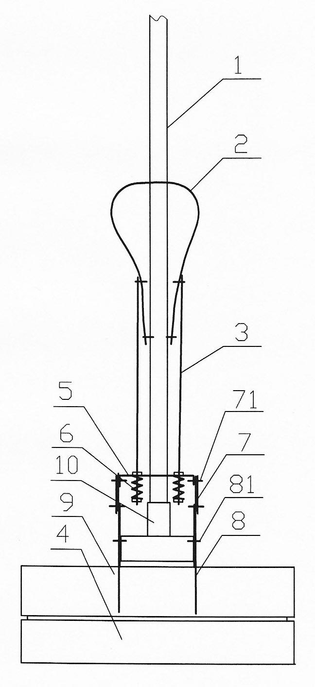
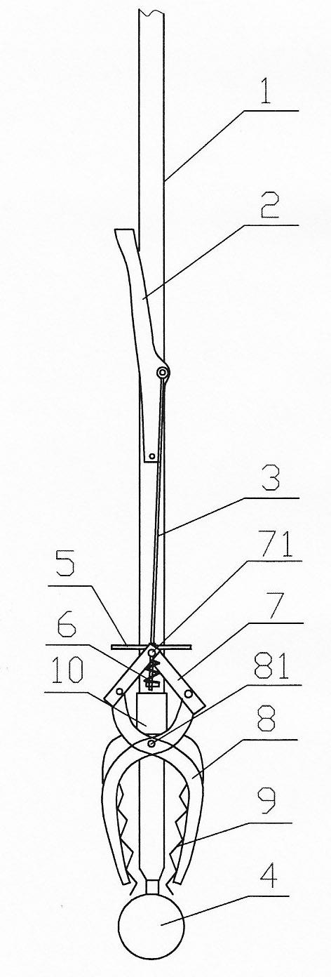
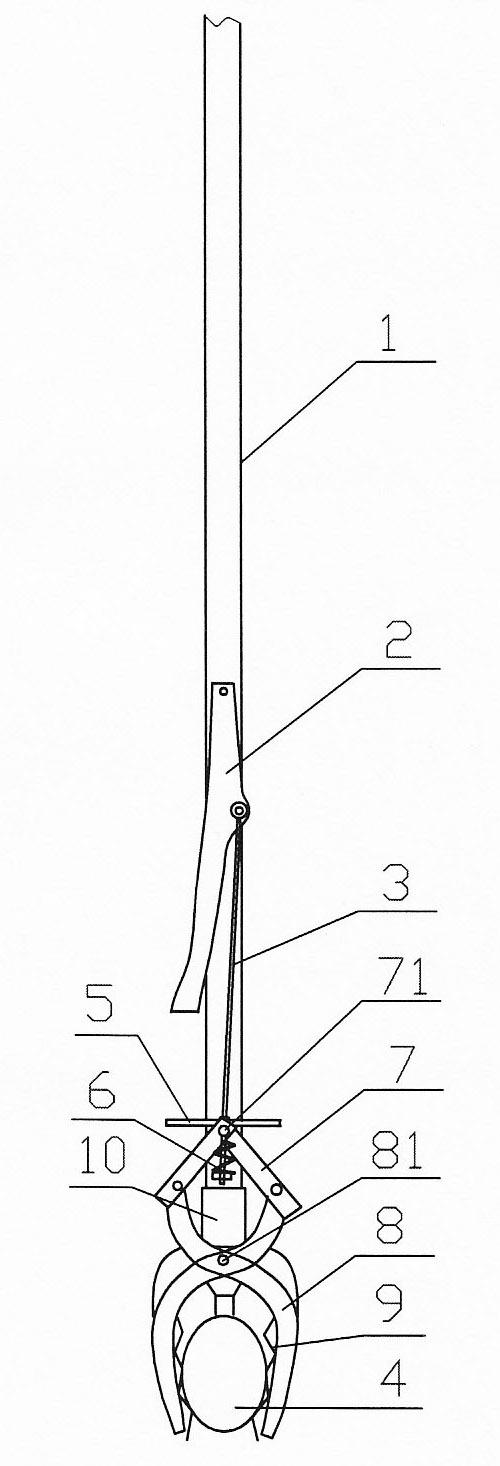
[0019] Such as Figure 1-5 Shown: a movable multifunctional collodion mop, including a mop rod 1, a handle 2, a push-pull rod 3, a collodion 4 and a movable dehydration clamping mechanism, the handle 2 is installed on the mop rod 1 through a connecting pin, and the push-pull rod The upper end of 3 is installed on the handle 2 through the connecting pin, the lower end is connected with the movable dehydration clamping mechanism, and the collodion 4 is installed at the bottom of the mop rod 1; the movable dehydration clamping mechanism is connected to include connecting plate 5, spring 6, connecting rod 7. Dehydration plate frame 8, dehydration plate 9 and rod cover 10 (if attached Figure 5 shown), there is a mop rod hole and a push-pull rod hole in the middle of the connecting plate 5, which is set on the mop rod 1, the lower end of the push-pull rod 3 is installed on the connecting plate 5 through the spring 6 and the nut, and the upper end of the connecting rod 7 is passed t...

Embodiment 2

[0022] Such as Figure 6 As shown: the collodion 4 of the present invention is wrapped with a mop 11, and the two ends of the mop 11 are clamped and fixed by the dehydration plate 9 of the movable dehydration clamping mechanism of the present invention, and the movable dehydration of the present invention can be loosened after mopping the ground. The dewatering plate 9 of the clamping mechanism removes the mop 11 to clean and dry. All the other structures are used in the same way as in Example 1.


PUM


Abstract

The invention discloses a movable multifunctional collodion cotton mop. The mop comprises a mop rod 1, a handle 2, a push-and-pull rod 3, collodion cotton 4 and a movable dewatering and clamping mechanism, wherein the upper end of the push-and-pull rod 3 is arranged on the handle 2 through a connecting pin, and the lower end of the push-and-pull rod 3 is connected with the movable dewatering and clamping mechanism; the collodion cotton 4 is arranged at the bottom of the mop rod 1; the movable dewatering and clamping mechanism is connected with a connecting plate 5, a spring 6, a connecting rod 7, a dewatering plate frame 8, a dewatering plate 9 and a rod sleeve 10; the connecting plate 5 is sleeved on the mop rod 1; the lower end of the push-and-pull rod 3 is arranged on the connecting plate 5 through the spring 6 and a nut; the upper end of the connecting rod 7 is connected with the connecting plate 5 through a connecting pin 71, and the lower end of the connecting rod 7 is connected with the upper end of the dewatering plate frame 8 through a connecting pin; the dewatering plate frame 8 is X-shaped and is arranged on the rod sleeve 10 through a connecting pin; the dewatering plate 9 is arranged on the X-shaped dewatering plate frame 8; and the rod sleeve 10 is sleeved on the mop rod 1. The mop disclosed by the invention has the advantages of complete dewatering, long service life, easiness of operation and the like.

Description

technical field [0001] The invention relates to a daily necessities, in particular to a movable multifunctional collodion mop. Background technique [0002] The mops used in the prior art include traditional cloth strip mops and collodion mops. The cloth strip mop has limited adsorption of dirt, and it is very inconvenient to wring out water or clean the mop strip. The dehydration or cleaning of the collodion mop is accomplished by pulling the handle on the mop rod so that the roller on the fork at the lower end of the mop rod extrudes the collodion, so the moisture in the mop collodion can be squeezed out more conveniently. Clean and clean. However, because the collodion clip at the lower end of the connecting rod connected with the handle is only connected with a small amount of collodion, and at the same time, because the fork for installing the roller is fixed, the width between the two rollers is fixed, which causes the following disadvantages: [0003] 1. Since the ...

Claims


Application Information

Patent Timeline
IPC IPC(8): A47L13/20A47L13/14
Inventor 张承志
Owner 张承志
Learn More