Vehicle roof system

A roof and roof panel technology, which is applied to the roof, vehicle parts, transportation and packaging, etc., can solve the problems of increasing manufacturing costs, limiting passengers' vision, and increasing the front and rear dimensions of the front frame, etc.

Active Publication Date: 2011-08-03
YACHIYO IND CO LTD
View PDF7 Cites 2 Cited by
  • Summary
  • Abstract
  • Description
  • Claims
  • Application Information

AI Technical Summary

Problems solved by technology

However, the molds used to mold the front frame become more complex, and this increases manufacturing costs
And, since the guide tube part formed in the front frame does not completely cover the push-pull cable, grease cannot be accommodated in the guide tube part, so the defined guide surface is not smooth enough
[0008] Also, when the guide tube portion is integrally formed with the front frame, the radius of curvature cannot be reduced as much as with conventional steel guide tubes
The resulting increase in frictional drag requires the use of a more powerful electric motor, which in turn results in a thicker roof
Also, the large radius of curvature requires an increase in the front and rear dimensions of the front frame, and this requires the leading edge of the roof window to be positioned farther back than desired
If the roof window is located too far back in the roof, the passenger's view through the roof window is too vertical, limiting the passenger's field of vision and reducing the benefits of the sunroof system

Method used


Image

  • Vehicle roof system
  • Vehicle roof system
  • Vehicle roof system

Examples


Embodiment Construction

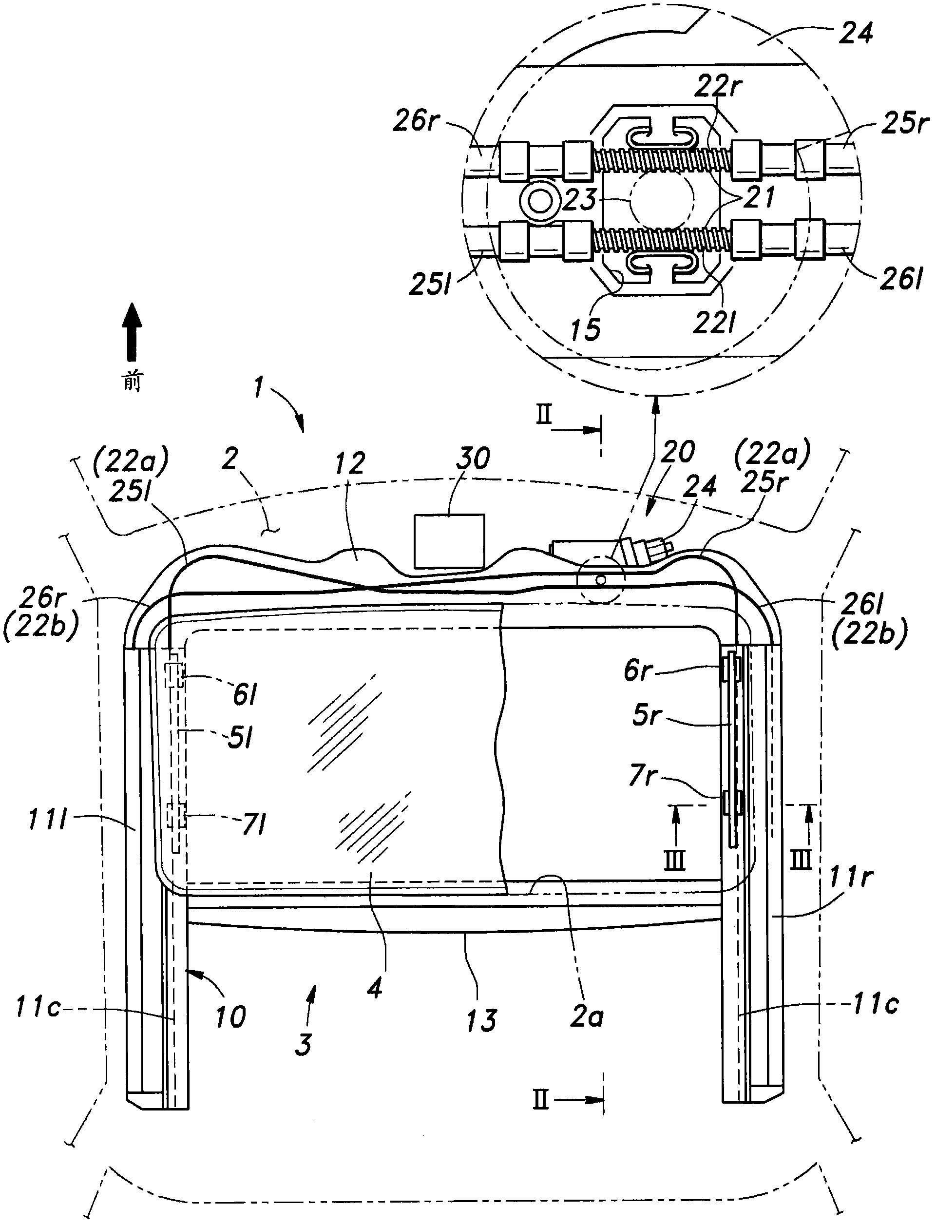
[0026] figure 1 is a transparent top view showing a roof system embodying the present invention. The illustrated roof 1 includes a fixed roof 2 and a sunroof system 3, the fixed roof 2 occupies most of the roof 1 and forms a rectangular window 2a at its front, the sunroof system 3 can selectively close and open the roof window 2a .

[0027] The majority of the roof system is symmetrical with respect to the central longitudinal plane of the body, and only one of the two symmetrical parts will be discussed below where appropriate, since the two symmetrical parts are substantially identical to each other. In some places, these symmetrical parts are indicated by a number with a suffix r or l to indicate which side of the body the part in question is located on. Elsewhere, these parts are generally indicated by the corresponding numeral without a suffix.

[0028] The sunroof system 3 includes a sunroof frame 10 fixedly fastened to the roof panel 2 and surrounding the roof window...


PUM


Abstract

The present invention discloses a vehicle roof system for closing and opening a roof opening (2a) formed in a fixed roof panel (2) of a vehicle with a moveable roof panel (4), in which an onboard device (30) is located in a laterally central part of the fixed roof panel (2) adjacent to a front edge of the roof opening, and an electric motor (24) for actuating the moveable roof panel is also located adjacent to the front edge of the roof opening but in a laterally offset and longitudinally overlapping relationship with the onboard device. As the electric motor and onboard device do not overlap each other in plan view, the thickness of the roof can be minimized. As the electric motor and onboard device overlap each other in side view, the distance between the upper edge of the front windshield and the front edge of the roof opening can be minimized, and this improves the field of view of the vehicle occupants.

Description

technical field [0001] The invention relates to a vehicle roof system comprising a movable roof and a drive unit for actuating the roof between a position closing a window in the roof and a position exposing the window. Background technique [0002] A roof system, also called a sunroof system, is widely used in passenger cars to selectively open and close a window formed in a roof. A typical vehicle roof system includes a movable roof and a drive unit for actuating the movable roof between a position for closing the window and a position for exposing the window. A pair of guide rails is fixedly fastened to the fixed top panel and extends along both sides of the roof window, and the movable top panel is supported by these guide rails via sliders so as to be slidable in the front-rear direction. An electric motor is located in the center of the front edge of the roof window, and a pair of push-pull cables connected to the corresponding slide is actuated by the electric motor ...

Claims


Application Information

Patent Timeline
Patent Type & Authority Applications(China)
IPC IPC(8): B60J7/04B60J7/057
CPCB60J7/057B60J7/022B60J7/043B60J7/04
Inventor 片山肇三桥步
Owner YACHIYO IND CO LTD
Why Eureka
Try Eureka