
Compressed trasmission belt

一种传动带、挤压式的技术,应用在V形带、皮带/链条/齿轮、机械设备等方向,能够解决摩擦力不稳定、刚性低、载荷分布易变得不均匀等问题,达到提高动力传递效率、抑制接触载荷的增大的效果

Inactive Publication Date: 2011-08-03
TOYOTA JIDOSHA KK
View PDF10 Cites 6 Cited by
  • Summary
  • Abstract
  • Description
  • Claims
  • Application Information

AI Technical Summary

Problems solved by technology

[0012] However, for example, a ring made of elastic body such as rubber or resin has moderate softness or flexibility, but when compared with a metal ring, its rigidity is relatively low, and the tension caused by the ring etc. and the distribution of the load acting on the saddle surface of the member tends to become uneven
Therefore, when a relatively low-rigidity rubber or resin ring is mounted on a member that has been convexly processed on the saddle surface as described in Japanese Patent No. 3406283, for example, the saddle shape of the member will The frictional force acting between the surface and the innermost peripheral surface of the ring becomes unstable, and effective centering or positioning may not be possible when a metal ring is used.

Method used


Image

  • Compressed trasmission belt
  • Compressed trasmission belt
  • Compressed trasmission belt

Examples


Embodiment Construction

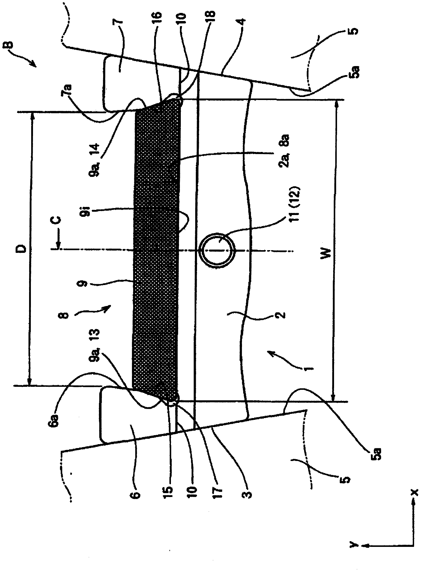
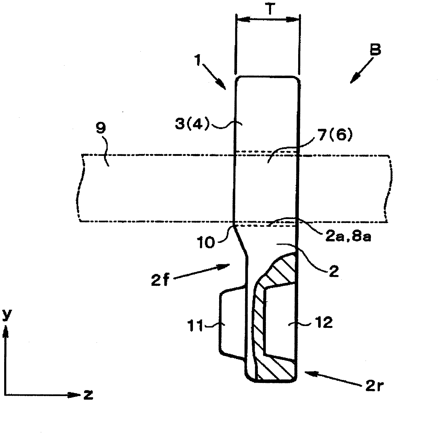
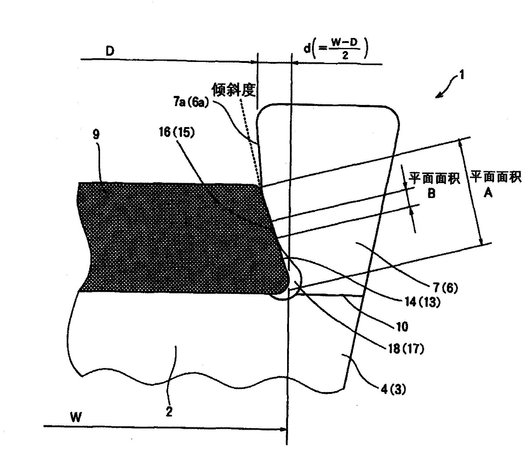
[0030] Next, the present invention will be specifically described with reference to the drawings. First, according to figure 1 , figure 2 The structure of the extrusion belt according to the present invention will be described. exist figure 1 , figure 2 shows an example in which the extruded belt B is, for example, wound around the drive side (input shaft) pulley and the driven side (output shaft) pulley of the belt type continuously variable transmission so that A belt that transmits power between the pulleys. Furthermore, the member 1 in the present invention is constituted by, for example, a metal plate-like member. On the body (base) portion 2 of the member 1, the belt width direction ( figure 1 The left and right side surfaces 3, 4 in the x-axis direction) are formed as tapered inclined surfaces. The tapered side surfaces 3 and 4 are in frictional contact with the belt winding groove (V-shaped groove) 5 a of the pulley 5 to transmit torque.

[0031] On the le...


PUM


Abstract

Provided is a compressed transmission belt capable of eliminating loss due to internal friction within a ring, properly aligning the ring with respect to an element and preventing uneven wear or degraded durability. The compressed transmission belt (B) comprises a flat element (1) having a recess (8) at the middle of the width at the external periphery thereof and a single layer belt ring (9) made of elastic material received in the recess (8). The belt ring (9) has a left side and a right side faces (9a, 9b) each slanted symmetrically with respect to a plane (C) at the middle of the width of the ring. The recess (8) has a left side and right side faces (15, 16) slanted similarly to the faces (13, 14) but having a smaller area of abutment to the element (1) than the slant faces (13, 14).

Description

technical field [0001] The present invention relates to a power transmission belt configured by arranging a plurality of plate-shaped members in an endless shape and assembling the plurality of members on a belt-shaped ring to form an endless shape, wherein the plurality of A plate-shaped member is formed with a concave portion for inserting a ring at the center portion in the belt width direction. The present invention particularly relates to an extruded transmission belt in which each member sequentially extrudes the front member so that the two Transmission of power between pulleys. Background technique [0002] As a belt for transmitting power used in a belt-type continuously variable transmission or the like, an extruded transmission belt is known. Usually, such extruded belts are constructed by aligning the postures of a plurality of plate-like small pieces (hereinafter referred to as members) called members or plates, arranged in an endless shape, and passing An ann...

Claims


Application Information

Patent Timeline
Patent Type & Authority Applications(China)
IPC IPC(8): F16G5/16
CPCF16G5/16
Inventor 佐野敏成
Owner TOYOTA JIDOSHA KK
Learn More