CT measurement with multiple X-ray sources

A technology of X-ray and measurement data, which is applied in the field of CT measurement using multiple X-ray sources, and can solve the problems that cannot be increased arbitrarily

Inactive Publication Date: 2011-08-10
SIEMENS AG
View PDF11 Cites 6 Cited by
  • Summary
  • Abstract
  • Description
  • Claims
  • Application Information

AI Technical Summary

Problems solved by technology

But this number is limited by the structure of the X-ray source, so it cannot be increased arbitrarily

Method used


Image

  • CT measurement with multiple X-ray sources
  • CT measurement with multiple X-ray sources
  • CT measurement with multiple X-ray sources

Examples


Embodiment Construction

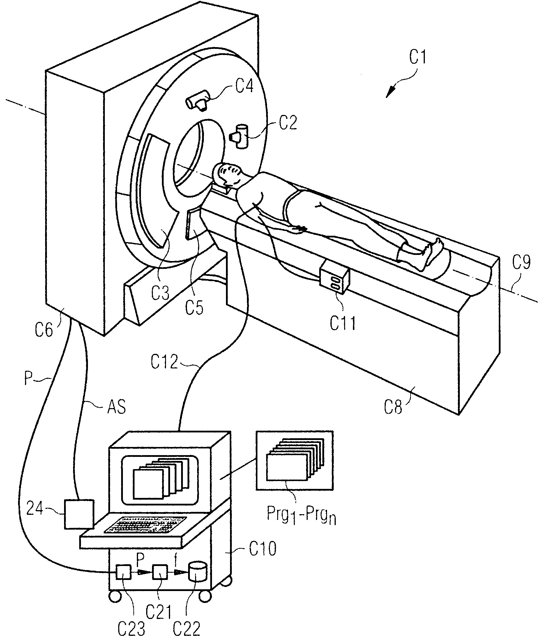
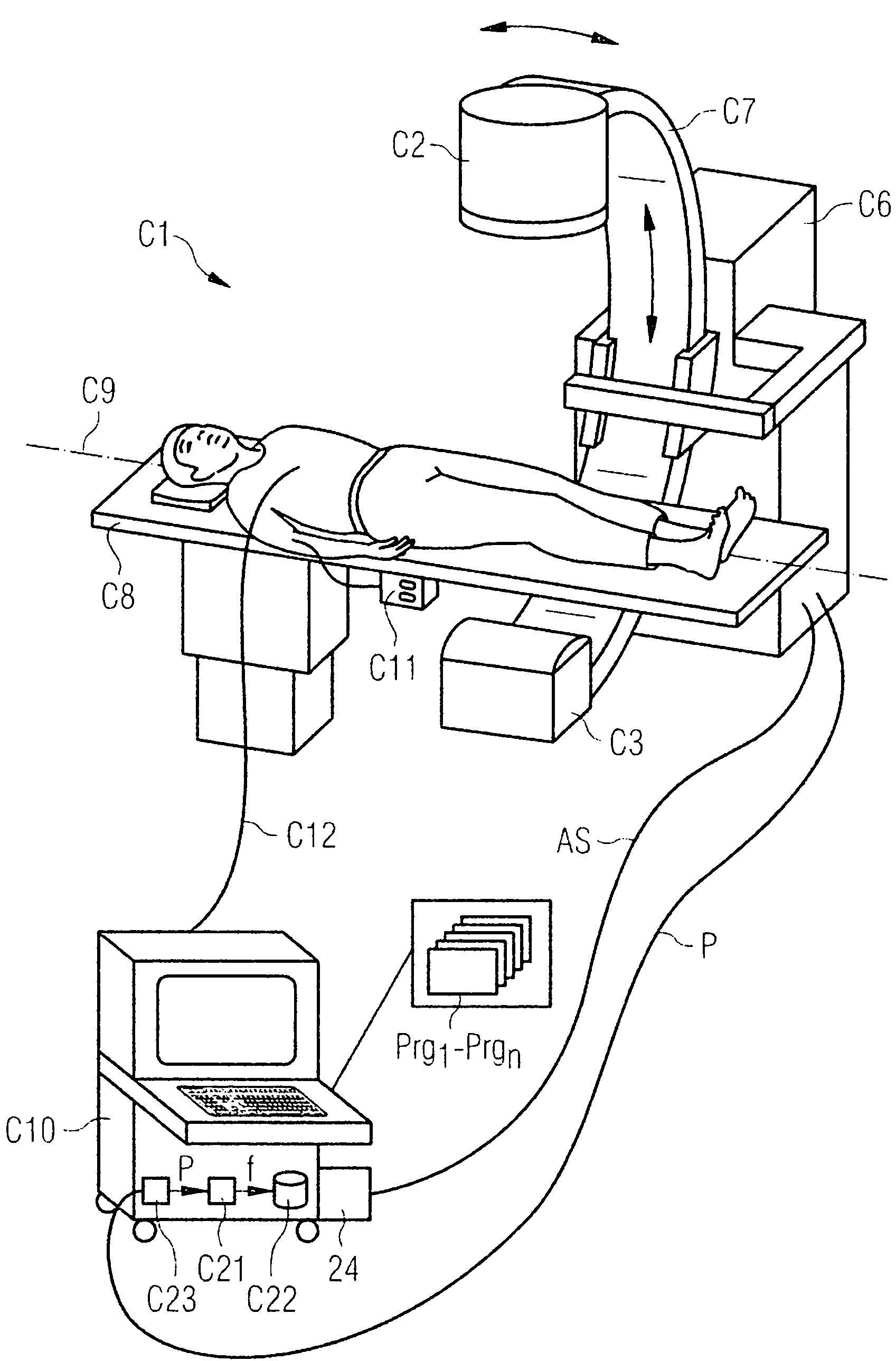
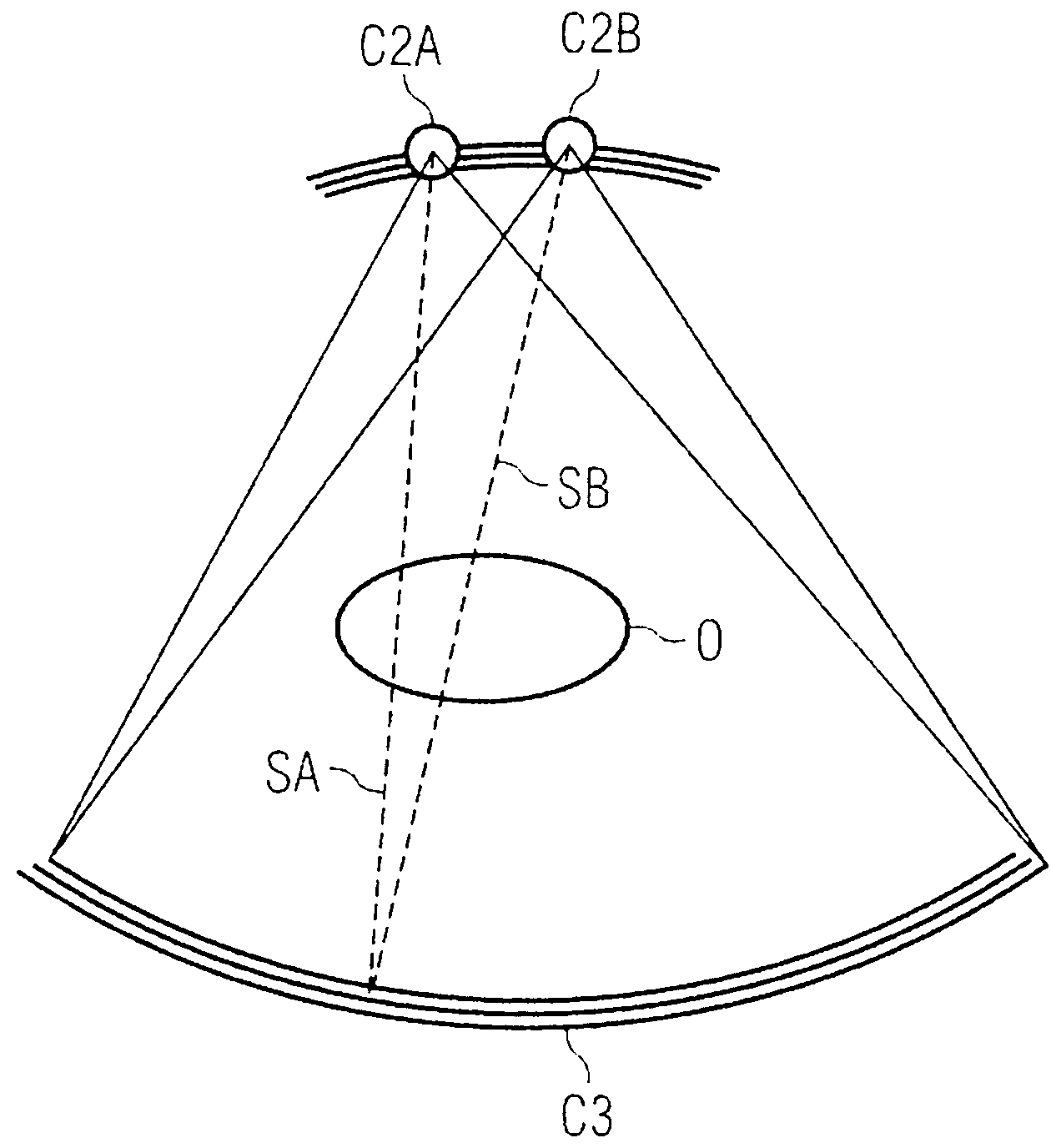
[0028] exist figure 1 In , firstly a first computed tomography system C1 with an image reconstruction device C21 is schematically shown. The computed tomography system is a so-called third-generation CT device, but the present invention is not limited thereto. A closing bracket (not shown here) is arranged in the bracket housing C6 , on which the first x-ray tube C2 and the opposite detector C3 are arranged. Optionally, a second X-ray tube C4 and an opposite detector C5 are provided in the CT system shown here, so that a higher temporal resolution can be achieved by an additionally provided emitter / detector combination, or in the radiation "Dual energy" inspections can also be performed where different X-ray energy spectra are used in the detector / detector system.

[0029]Furthermore, the CT system C1 has a patient table C8 on which the patient can be moved into the measurement field during the examination along the system axis C9 (also referred to as the Z axis), wherein th...


PUM


Abstract

A method is disclosed for reconstructing image data of an examination object (O) from measurement data of a computed tomography system, the examination object (O) having been irradiated simultaneously by a number of X-ray sources while the measurement data was being acquired so that different projections of the examination object (O) associated with the number of X-ray sources (C2A, C2B) were acquired simultaneously for each detector element. In at least one embodiment, different iteration images of the examination object are determined one after the other from the measurement data by way of an iterative algorithm, a computation operation being employed with the iterative algorithm, which is applied to the iteration images and takes the presence of the number of X-ray sources (C2A, C2B) into account.

Description

technical field [0001] The invention relates to a method for acquiring measurement data with a computed tomography system and a method for reconstructing image data of an examination object from these measurement data. Background technique [0002] Methods of scanning an examination object using a CT system are generally known. In this case, for example, circular scanning, sequential circular scanning with feed (Vorschub) or helical scanning is used. Other types of scans that are not based on circular motion, such as scans with linear segments, may also be used. Absorption data of the examination object are recorded from different recording angles by means of at least one x-ray source and at least one detector arranged opposite, and the absorption data or projections thus collected are calculated as cross-sectional images through the examination object by means of a corresponding reconstruction method . [0003] In order to reconstruct computed tomography images from the ...

Claims


Application Information

Patent Timeline
Patent Type & Authority Applications(China)
IPC IPC(8): A61B6/03G06F19/00
CPCA61B6/507G06T11/006A61B6/4014A61B6/032A61B6/481A61B6/482G06T2211/424A61B6/466A61B5/0402A61B6/504
Inventor 赫伯特・布鲁德卡尔・斯蒂尔斯托弗
Owner SIEMENS AG
Why Eureka
Try Eureka