Cutter frame for machining large end of loose joint

A technology for processing knives and tool holders, which is applied in the field of tool holders, can solve problems such as slow processing speed and poor product sealing function, and achieve the effect of improving efficiency

Active Publication Date: 2012-07-04
JINAN MEIDE CASTING CO LTD
View PDF0 Cites 0 Cited by
  • Summary
  • Abstract
  • Description
  • Claims
  • Application Information

AI Technical Summary

Problems solved by technology

The processing speed is slow in this way, and the sealing function of the product is poor

Method used


Image

  • Cutter frame for machining large end of loose joint
  • Cutter frame for machining large end of loose joint
  • Cutter frame for machining large end of loose joint

Examples


Embodiment 1

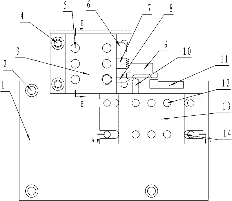
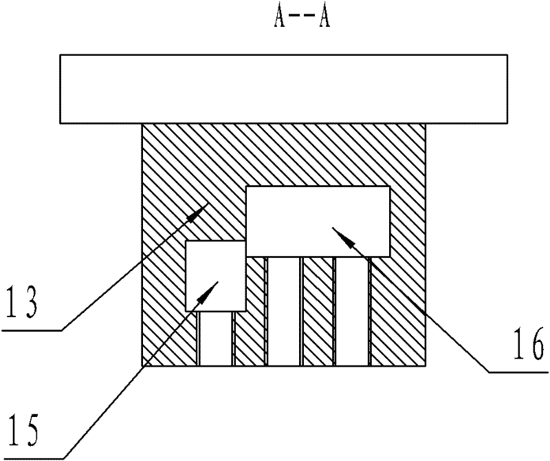
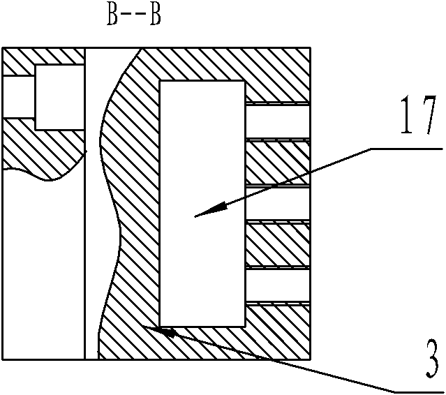
[0014] Embodiment 1, a kind of tool rest of processing live joint big head, its structure is: as figure 1 The convex tool holder bottom plate 1 shown in the figure is equipped with a mutually vertical outer circle processing tool mounting frame 3 and an end surface processing tool mounting frame 13, and the outer circle processing tool mounting frame is fixed on the protrusion of the tool frame bottom plate by the mounting frame fixing bolt 4 , The end face processing tool mounting frame is fixed on the lower right side of the outer circle processing tool mounting frame, and the end face processing tool mounting frame base two ends are provided with mounting frame positioning grooves 14, and fixing bolts are housed in the grooves.

[0015] There is an outer circle machining tool mounting hole 17 in the middle of the outer circle processing tool mounting frame, and a tool fixing bolt 5 is arranged on the top, and a 45 degree partial knife mounting hole 15 and an end face knife m...


PUM


Abstract

The invention discloses a cutter frame for machining a large end of a loose joint, belonging to a cutter frame of a lathe for machining, in particular to a cutter mounting device capable of machining two vertical machining faces. The cutter frame for machining the large end of the loose joint is characterized in that a convex cutter frame base plate is provided with an excircle machining cutter mounting frame and an end face machining cutter mounting frame which are vertical mutually, wherein the excircle machining cutter mounting frame is fixed on a convex head of the cutter frame base plateby using mounting frame fixing bolts, and two ends of a base of the end face machining cutter mounting frame are provided with mounting frame locating grooves in which fixing bolts are arranged. The invention has the beneficial effects that the number of machining steps is reduced to three from five originally, the cutter frame is simple to operate and convenient to master, and the efficiency is increased by about 40%; and because cutter fixing and mounting are realized, labor location is less in operation, thereby being favorable for improving the quality of products. The cutter frame in thetechnical scheme provided by the invention can be used for other parts with excircles and end faces needing to be machined by making slight changes.

Description

technical field [0001] The invention belongs to a tool holder of a lathe for mechanical processing, in particular a tool mounting device capable of processing two vertical processing surfaces. Background technique [0002] The union is one of the most commonly used pipeline connectors. It is used in a large amount, and the bulk of the union needs to be processed. Method: The knife rod is a small knife rod used, installed on a square tool holder, and a total of 3 knives are installed: a stripping knife (for processing the large diameter of the thread and an angle of 45 degrees outside), a comb knife (for processing the thread), and a straight knife (for processing the large end The end face and copper pad)" original processing method: the first step: turn the hand wheel of the horizontal knife, and process the 45-degree chamfer of the big head with the light knife; the second step: turn the hand wheel of the horizontal knife and the hand wheel of the vertical knife, use The ...

Claims


Application Information

Patent Timeline
Patent Type & Authority Patents(China)
IPC IPC(8): B23B29/24
Inventor 任艳清刘根群郭雷张明远
Owner JINAN MEIDE CASTING CO LTD
Why Eureka
Try Eureka