Flat heat radiating pipe and manufacturing method thereof

A manufacturing method and heat dissipation pipe technology, applied in the field of heat dissipation, can solve the problems that the working medium delivery capacity of the heat dissipation pipe cannot be fully supplemented, the capillary structure is prone to deformation, disintegration, and the working medium delivery capacity is reduced, so as to prevent the maximum transmission Great reduction of heat, prevention of increase in thermal resistance, and effect of increasing heat transfer efficiency

Inactive Publication Date: 2011-08-10
KUN SHAN DOTOP METAL TECH CO LTD
View PDF1 Cites 20 Cited by
  • Summary
  • Abstract
  • Description
  • Claims
  • Application Information

AI Technical Summary

Problems solved by technology

[0006] The problem solved by the present invention is that the heat dissipation pipe adopts a single capillary structure. When the heat dissipation pipe is flattened, the capillary structure is prone to deformation and disintegration, which greatly reduces the working medium delivery capacity of the entire heat dissipation pipe. Sufficiently supplemented, resulting in a substantial decrease in the maximum heat transfer of the heat pipe and an increase in thermal resistance

Method used


Image

  • Flat heat radiating pipe and manufacturing method thereof
  • Flat heat radiating pipe and manufacturing method thereof
  • Flat heat radiating pipe and manufacturing method thereof

Examples


Embodiment Construction

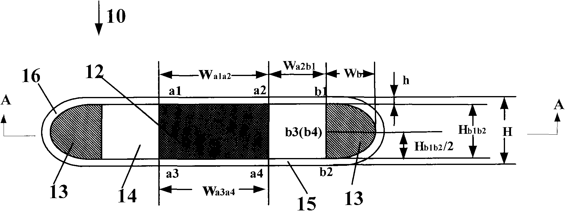
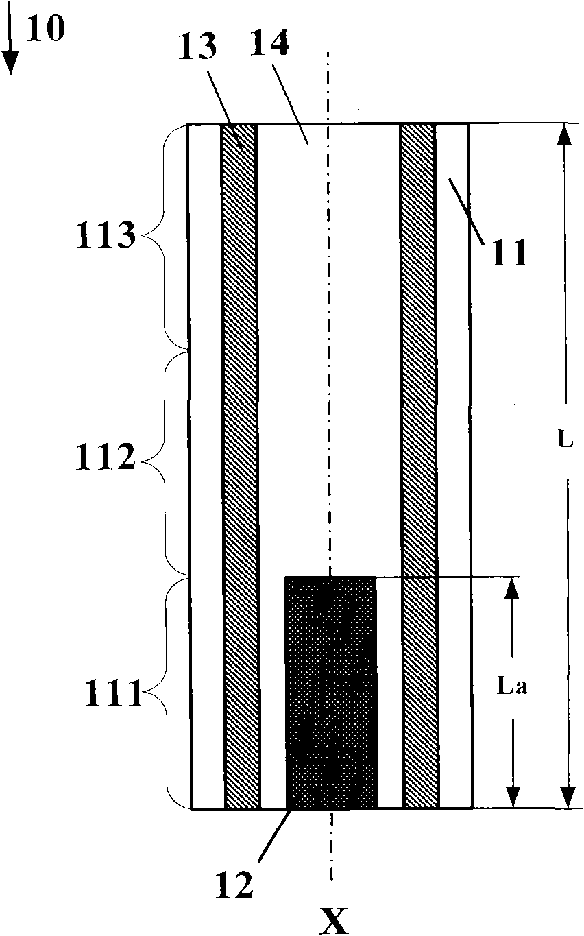
[0042] The embodiment of the present invention provides a flat heat dissipation pipe, which contains a composite capillary structure, that is, includes a main capillary structure and an auxiliary capillary structure, which improves the capillary force of the heat dissipation pipe and increases the delivery capacity of the working medium, thereby increasing the heat of the heat dissipation pipe Transmission efficiency; especially in the evaporation section of the flat heat pipe with high flatness requirements, there will be no obvious depressions, which ensures that the gas passage of the ultra-thin heat pipe after flattening has enough space. The specific implementation of the present invention will be combined with the accompanying drawings below method in detail.

[0043] figure 2 It is a schematic cross-sectional view of the flat heat pipe in the evaporation section perpendicular to the axial direction of the embodiment of the present invention, image 3 yes figure 2 Th...


PUM

PropertyMeasurementUnit
thicknessaaaaaaaaaa
thicknessaaaaaaaaaa
thicknessaaaaaaaaaa

Abstract

The invention discloses a flat heat radiating pipe which comprises a pipe cavity with two closed ends and a pipe wall enclosing the pipe cavity along the axial direction, wherein the pipe wall comprises arc walls positioned at two sides and a flat wall for connecting the arc walls, the pipe cavity and the pipe wall are sequentially defined as an evaporation section, a heat insulation section and a condensation section along the axial direction; the pipe cavity is internally provided with a main capillary structure and an auxiliary capillary structure, wherein the main capillary structure is in contact with the flat wall of the evaporation section or in contact with the flat walls of the evaporation section and the heat insulation section; the auxiliary capillary structure is in contact with the arc wall positioned at least one side, the pipe cavity between the main capillary structure and the auxiliary capillary structure is filled with a working medium; and a main gas channel of a heat radiating pipe has enough space so that capillary force of the flat heat radiating pipe is improved and conveying capacity of the working medium is increased, and thus heat transfer efficiency of the flat heat radiating pipe is increased. The invention also provides a manufacturing method of the flat heat radiating pipe.

Description

technical field [0001] The invention relates to heat dissipation technology, in particular to a flat heat dissipation pipe and a manufacturing method thereof. Background technique [0002] Today's electronic products tend to develop in the direction of thinner, thinner and smaller. The heat dissipation problem of electronic products in the ever-shrinking space becomes more and more important. This requires heat dissipation products to have higher heat transfer and heat dissipation performance while becoming thinner and smaller. [0003] Due to the advantages of high heat transfer, heat pipes have been widely used in electronic components with large heat generation. When the heat pipe is working, the low-boiling-point working medium filled inside the heat pipe absorbs the heat generated by the heating electronic components in the evaporation section of the heat pipe, evaporates and vaporizes, and moves to the condensation section with heat through the adiabatic section, and l...

Claims


Application Information

Patent Timeline
Patent Type & Authority Applications(China)
IPC IPC(8): F28D15/04B23P15/26
Inventor 朱胜利
Owner KUN SHAN DOTOP METAL TECH CO LTD
Why Eureka
Try Eureka