Injection molding machine

An injection molding machine and injection tube technology, applied in the field of injection molding machines, can solve the problems affecting the molding quality of products, the slow progress of the pushing process, and the impact on production efficiency, and achieve the effects of not easy to deform, improve production efficiency, and ensure quality.

Inactive Publication Date: 2015-09-23
NANJING BLESSED HYDRAULIC MACHINERY
View PDF0 Cites 4 Cited by
  • Summary
  • Abstract
  • Description
  • Claims
  • Application Information

AI Technical Summary

Problems solved by technology

[0002] Injection molding machine is a very common machine in modern industrial production. Its principle is to heat the plastic raw material to melt it to obtain a melt formed by the plastic raw material. The injection molding machine then injects the obtained melt into the plastic mold. Then use the hydraulic cylinder to drive the upper mold to press down the lower mold. After the pressing is completed, the lower mold is cooled. After cooling, the corresponding plastic products can be obtained. However, the injection tubes used to melt plastic raw materials in existing injection molding machines are usually The inner wall is very smooth, so that the screw used to push the plastic material is easy to drive the plastic material to rotate around the screw during the process of rotating and pushing, which makes the progress of the whole pushing process quite slow, and the production efficiency is also greatly affected. The pressure of the melt in the mold is too small, and the melt is prone to deformation during the cooling process, which seriously affects the molding quality of the product.

Method used


Image

  • Injection molding machine

Examples


Embodiment Construction

[0010] Below in conjunction with accompanying drawing and specific embodiment, further illustrate the present invention, should be understood that these embodiments are only for illustrating the present invention and are not intended to limit the scope of the present invention, after having read the present invention, those skilled in the art will understand various aspects of the present invention Modifications in equivalent forms all fall within the scope defined by the appended claims of this application.

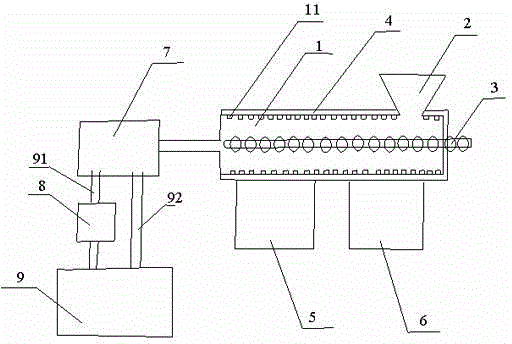
[0011] Such as figure 1 As shown, the present invention provides a kind of injection molding machine, comprises the injection molding pipe 1 that is provided with feed inlet 2, the screw rod 3 that is positioned at injection molding pipe 1, injection mold 7 and cooling water tank 9, uniform on the inner wall of described injection molding pipe 1 Several bumps 11 are provided, the outer surface of the injection molding pipe 1 is provided with a thermal insulation layer 4,...


PUM


Abstract

The invention discloses an injection molding machine which comprises an injection molding pipe provided with a feed port, a screw rod positioned in the injection molding pipe, an injection mold and a cooling water tank, wherein a plurality of convex blocks are uniformly arranged on an inner wall of the injection molding pipe; a heat preservation layer is arranged on the outer surface of the injection molding pipe; the injection molding pipe is connected with a strong heating electricity box and a weak heating electricity box; the cooling water tank is communicated with the injection mold mutually through a water inlet pipe and a water outlet pipe; and an air compressor is arranged on the water inlet pipe. The injection molding machine shortens the service time of a material pushing process, and improves the production efficiency of a product; the air compressor can provide high pressure to cooling water, to allow that no melt in the mold deforms easily in a cooling process; and the quality of the product is ensured.

Description

technical field [0001] The invention specifically relates to an injection molding machine. Background technique [0002] Injection molding machine is a very common machine in modern industrial production. Its principle is to heat the plastic raw material to melt it to obtain a melt formed by the plastic raw material. The injection molding machine then injects the obtained melt into the plastic mold. Then use the hydraulic cylinder to drive the upper mold to press down the lower mold. After the pressing is completed, the lower mold is cooled. After cooling, the corresponding plastic products can be obtained. However, the injection tubes used to melt plastic raw materials in existing injection molding machines are usually The inner wall is very smooth, so that the screw used to push the plastic material is easy to drive the plastic material to rotate around the screw during the process of rotating and pushing, which makes the progress of the whole pushing process quite slo...

Claims


Application Information

Patent Timeline
Patent Type & Authority Applications(China)
IPC IPC(8): B29C45/62B29C45/73B29C45/50
CPCB29C45/62B29C45/50B29C45/73
Inventor 陈海楼
Owner NANJING BLESSED HYDRAULIC MACHINERY
Why Eureka
Try Eureka