Method for simulation of welding distortion

An analysis method and welding deformation technology, applied in welding equipment, instruments, electrical and digital data processing, etc., can solve problems such as application limitations and inability to use two-dimensional models, and achieve the effect of shortening calculation time and improving calculation accuracy.

Inactive Publication Date: 2011-08-17
HITACHI LTD
View PDF7 Cites 21 Cited by
  • Summary
  • Abstract
  • Description
  • Claims
  • Application Information

AI Technical Summary

Problems solved by technology

However, for the welding deformation of complex large-scale structures, in many cases, the two-dimensional model cannot be used, and there is a problem that the application is limited

Method used


Image

  • Method for simulation of welding distortion
  • Method for simulation of welding distortion
  • Method for simulation of welding distortion

Examples


Embodiment 1

[0072] Next, as Example 1, a case where the analysis method of this embodiment is applied to a specific welded structure with a fixed shape will be described.

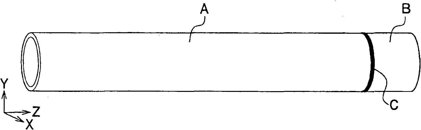
[0073] image 3 It is a diagram showing the structure of the welded structure to be analyzed. The welded construction is a tubular construction. Consists of ring welding C of material A to be welded and material B to be welded. The structure after welding has a length of about 5m, a diameter of about 200mm, and a thickness of 7mm to 13mm.

[0074] by putting image 3 The shown welded structure is modeled by finite element, a three-dimensional model is generated, and an overall model is constructed by performing a mesh generation step (one of the processes performed by the model generation and processing unit 142 ).

[0075] Figure 4 yes means image 3 An illustration of the overall model of the welded structure. The overall model is composed of a partial model 4 (represented by mesh) and the remaining part 5 of...

Embodiment 2

[0111] Next, as Example 2, another case where the analysis method of the present embodiment is applied to a welded structure with a specific shape will be described. The second embodiment is an example of the case where the setting of the constraint condition of the boundary portion in the first embodiment is changed.

[0112] The analysis object of this embodiment is identical with the object used in embodiment 1, is image 3 Tubular welded construction shown. In addition, the analysis method is the same as that of the first embodiment except for the processing related to the setting of the constraint condition of the boundary portion. That is, the analysis method of Example 2 includes: firstly, the structure as the analysis object is made into an overall model through the process of generating a mesh; A process of extracting from the overall model of the welded structure necessary for the analysis; a process of performing a thermoelastoplastic analysis on the local model w...


PUM

PropertyMeasurementUnit
lengthaaaaaaaaaa
diameteraaaaaaaaaa
thicknessaaaaaaaaaa

Abstract

It is an object of the present invention to accomplish both improvement of a calculation precision and reduction of a calculation time in prediction of a welding distortion of a large welded structure. A method of modeling a welded structure subjected to analysis by generating a mesh and performing thermo-elastic-plastic analysis thereon constructs a global model of the welded structure, and extracts a local model including a welded part from the global model. Next, the method constrains a boundary part of the extracted local model with the remaining portion of the global model, performs thermo-elastic-plastic analysis, and pastes the local model including the analysis result of the thermo-elastic-plastic analysis on the remaining portion of the global model, thereby reconstructing the global model. Thereafter, the method releases the constraint on the boundary part, and performs elastic analysis on the global model, thereby calculating a distortion of the welded structure.

Description

technical field [0001] The present invention relates to a technique for calculating deformation, residual stress, and the like of a welded structure (sometimes simply referred to as a "structure") by numerical analysis. Background technique [0002] When a large-scale structure is manufactured by welding construction, welding deformation occurs due to heat accumulation in the vicinity of the welded portion and subsequent cooling. In order to reduce this welding distortion, installation of restraining jigs, post-welding correction work, and the like are generally performed. In this case, it is extremely important to improve production efficiency and reduce costs by predicting deformation using numerical analysis such as the finite element method to optimize response to deformation. [0003] Welding deformation analysis using the finite element method is roughly divided into two methods: thermoelastoplastic analysis and intrinsic strain method. Welding deformation analysis u...

Claims


Application Information

Patent Timeline
Patent Type & Authority Applications(China)
IPC IPC(8): B23K31/12B23K31/00G06F17/50
CPCG06F2217/80G06F17/5018G06F30/23G06F2119/08
Inventor 张旭东
Owner HITACHI LTD
Why Eureka
Try Eureka