
Positive pressure pneumatic conveying system and method

A pneumatic conveying system and pneumatic conveying technology, applied to conveyors, conveying bulk materials, transportation and packaging, etc., can solve problems such as increased air consumption, poor adaptability to changes, and decreased conveying output, and achieve the effect of improving conveying force

Active Publication Date: 2011-08-17
克莱德贝尔格曼华通物料输送有限公司
View PDF10 Cites 12 Cited by
  • Summary
  • Abstract
  • Description
  • Claims
  • Application Information

AI Technical Summary

Problems solved by technology

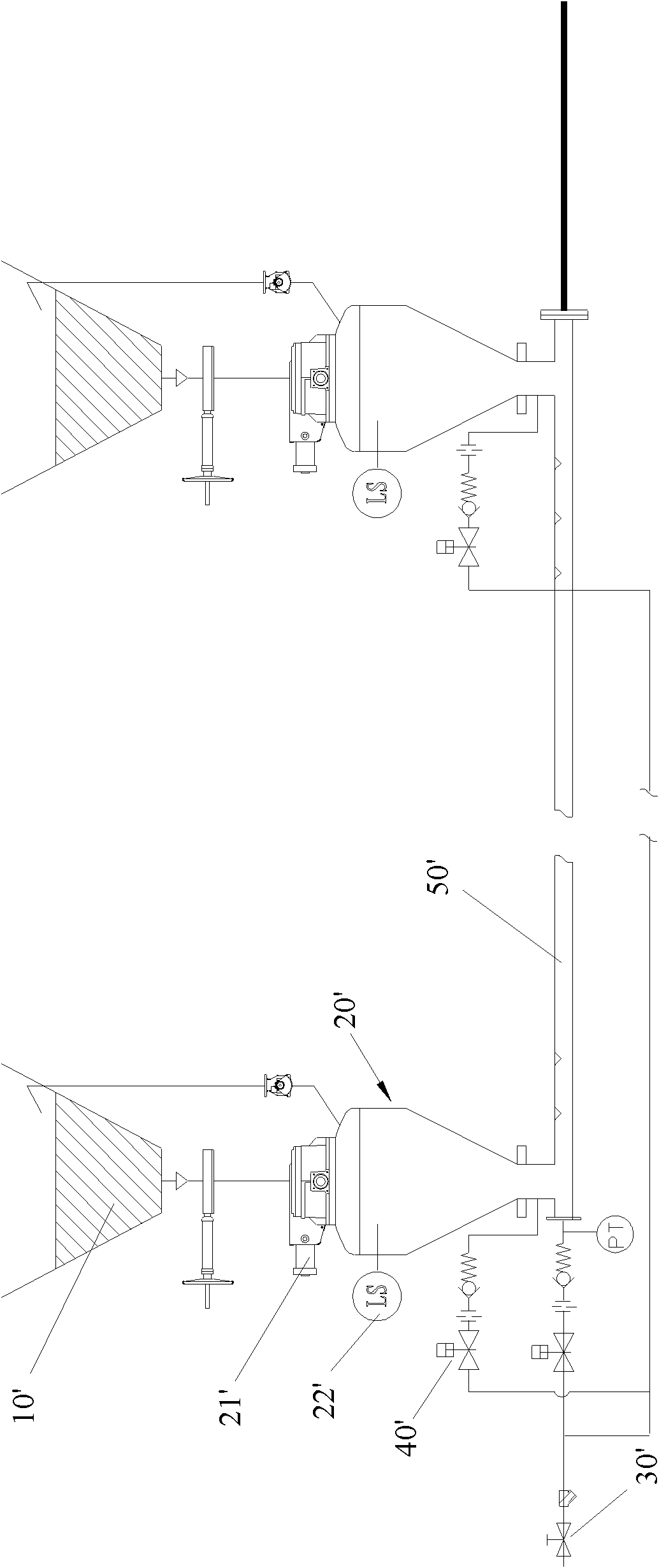
[0004] The existing positive pressure pneumatic conveying system has weak conveying power. For the electric field coarse ash produced by the electric dust collector of the poor coal-fired boiler, the conveying output decreases and the gas consumption increases; Settled ash, difficult to transport, poor adaptability to changes in various working conditions

Method used


Image

  • Positive pressure pneumatic conveying system and method
  • Positive pressure pneumatic conveying system and method
  • Positive pressure pneumatic conveying system and method

Examples


Embodiment Construction

[0024] The present invention will be described in detail below with reference to the accompanying drawings and in combination with embodiments.

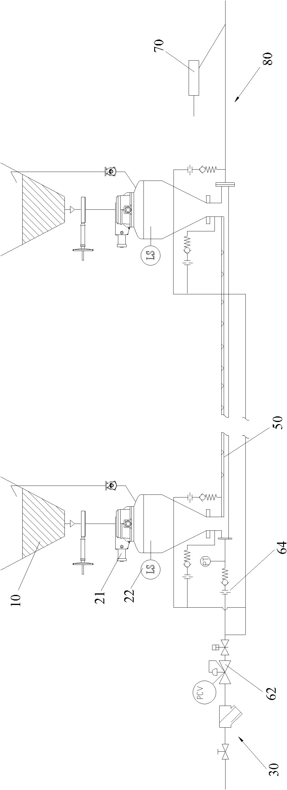
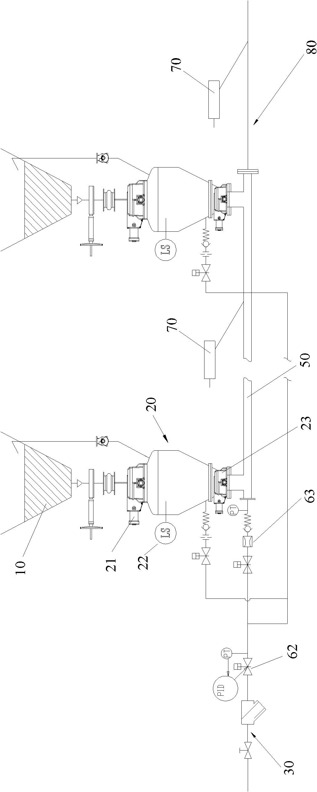
[0025] According to the positive pressure pneumatic conveying system of the present invention, such as figure 2 As shown in FIG. 5 , the main air intake pipeline 30 is included, and its first end communicates with the first compressed air source; the delivery pipeline 50 has a first end communicated with the main air intake pipeline 30; a plurality of warehouse pumps 20, The lower ends of multiple warehouse pumps 20 are connected with the conveying pipeline 50; an air volume regulating device is also included, and the air volume regulating device includes: a pressure regulating valve 62, which is arranged on the main air intake pipe 30; Downstream of the pressure regulating valve 62 on the gas pipeline 30, the gas flow through it is adjusted according to the post-valve pressure value of the pressure regulating valve 62; the pipeline...


PUM


Abstract

The invention provides a positive pressure pneumatic conveying system and method. The positive pressure pneumatic conveying system disclosed by the invention also comprises an air flow adjusting device. The air flow adjusting device comprises an adjusting valve, an air flow adjusting element and a pipeline air supplementing device, wherein the adjusting valve is arranged on a main air inlet pipeline; the air flow adjusting element is arranged on the downstream of the adjusting valve on the main air inlet pipeline and is used for adjusting air flow passing through the air flow adjusting element according to a downstream pressure value of the adjusting valve; and the pipeline air supplementing device is matched with the air flow adjusting device to adjust the final air flow of the pipeline.The positive pressure pneumatic conveying method disclosed by the invention comprises the following steps of: charging a plurality of bin pumps; charging compressed air into an air inlet pipeline; adjusting the pipeline pressure in the air inlet pipeline by adjusting a pressure adjusting valve arranged on the air inlet pipeline; adjusting air flow passing through the air flow adjusting element bythe air flow adjusting element arranged on the air inlet pipeline according to the downstream pressure value of the adjusting valve arranged upstream; and supplementing compressed air into the conveying pipeline.

Description

technical field [0001] The present invention relates to the field of material conveying, more specifically, to a positive pressure pneumatic conveying system and method. Background technique [0002] The pneumatic conveying system adopts the principle of gas-solid two-phase flow, uses compressed air as the medium and power of conveying materials, and conveys powdery materials to remote collection points. Pneumatic conveying technology is divided into negative pressure pneumatic conveying, low positive pressure pneumatic conveying, positive pressure pneumatic conveying, etc. The positive pressure pneumatic conveying system has been widely used due to its advantages of low air consumption, large conveying output, and small pipeline wear. [0003] The positive pressure pneumatic conveying system in the prior art adopts the method of connecting multiple warehouse pumps in series, taking the positive pressure pneumatic conveying system under the ash hopper of the electrostatic p...

Claims


Application Information

Patent Timeline
IPC IPC(8): B65G53/66
Inventor 肖为农孔祥云雷景贵叶坤
Owner 克莱德贝尔格曼华通物料输送有限公司
Learn More