
Braking system and a method for braking a vehicle in the case of abrupt changes in the friction coefficient

a technology of braking system and friction coefficient, which is applied in the direction of braking system, process and machine control, instruments, etc., can solve the problems of vehicle being known to be unstable, unsteerable and unstable, and lowering the pressure of the brake master cylinder, so as to reduce the standstill period of the wheels

Inactive Publication Date: 2013-09-26
ROBERT BOSCH GMBH
View PDF2 Cites 6 Cited by
  • Summary
  • Abstract
  • Description
  • Claims
  • Application Information

AI Technical Summary

Benefits of technology

This patent is about a brakes system for vehicles that reduces the time it takes for the wheels to stop when using ABS brakes. The system achieves this by reducing the boost of the brakes during braking maneuvers on surfaces with sudden changes in friction. By doing so, the system reduces the pressure on the engine and allows for faster braking. This is achieved without the need to increase the size of the brakes storage area or the return pump. In addition, by reducing the boost of the brakes, the system reduces the energy needed for the brakes to stop, which results in less wear and tear on the brakes. This is particularly useful when braking on surfaces with sudden changes in friction, like in snow or on a track. Overall, this system improves the performance and durability of brakes on vehicles.

Problems solved by technology

In certain braking situations, e.g., emergency braking actions in which a relatively high brake pressure acts on the wheel brakes, it may occur that the return pump is not capable of conveying the brake fluid back fast enough, resulting in the storage chamber filling up.
In this state, the vehicle is known to be unsteerable and becomes unstable.
In principle, it would be possible to enlarge the storage chamber or the return pump, but this is uneconomical for cost reasons and thus undesirable.
Since in the case of an ABS control the return pump works against the brake pressure generated in the brake master cylinder, a reduction of the brake boost results in a lower brake master cylinder pressure and thus in a smaller load on the return pump.
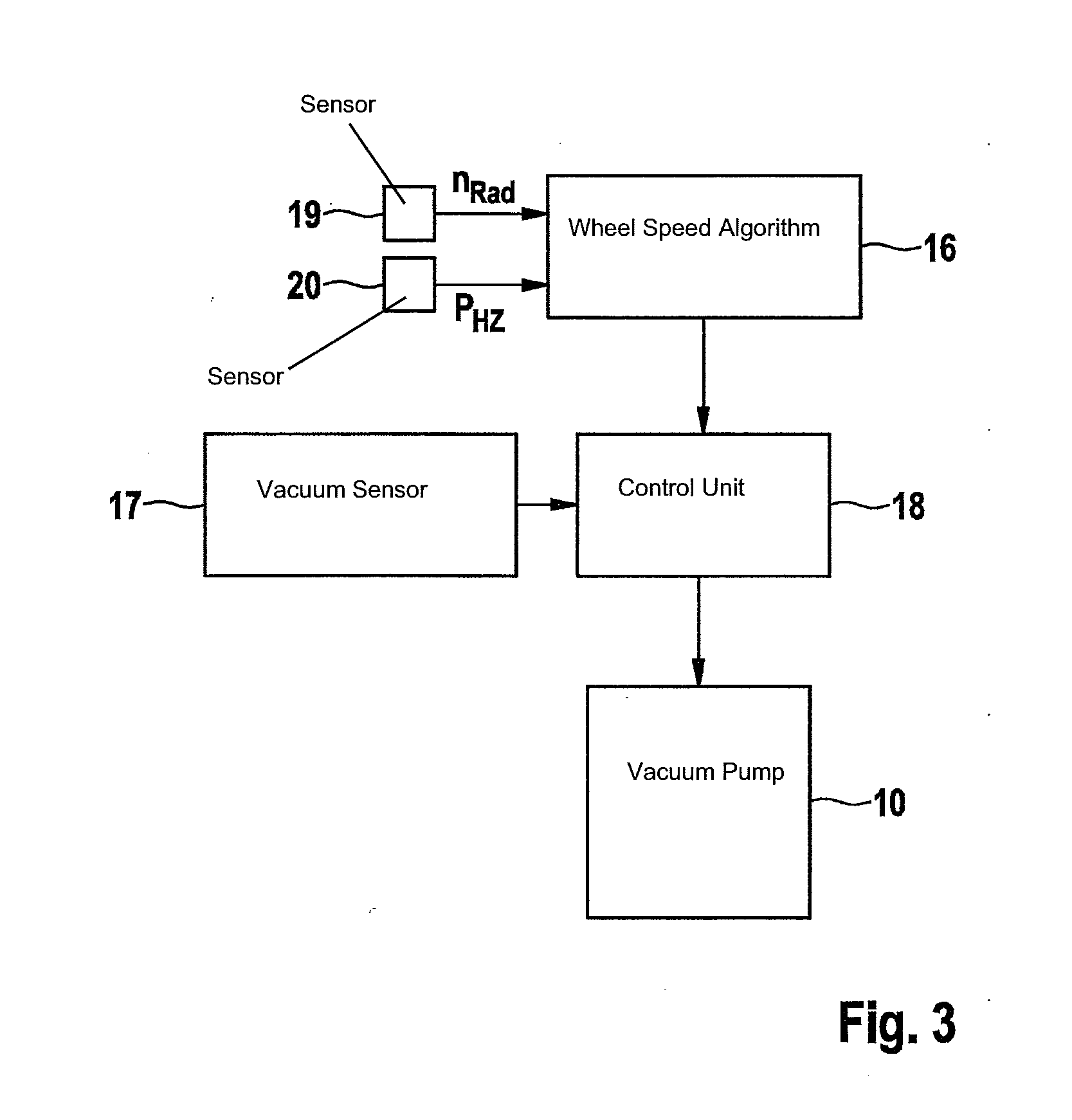
In the case of a very low absolute pressure, the vacuum pump is not or is only able to start with a delay during an ABS control, as mentioned previously.

Method used


Image

  • Braking system and a method for braking a vehicle in the case of abrupt changes in the friction coefficient
  • Braking system and a method for braking a vehicle in the case of abrupt changes in the friction coefficient
  • Braking system and a method for braking a vehicle in the case of abrupt changes in the friction coefficient

Examples


Embodiment Construction

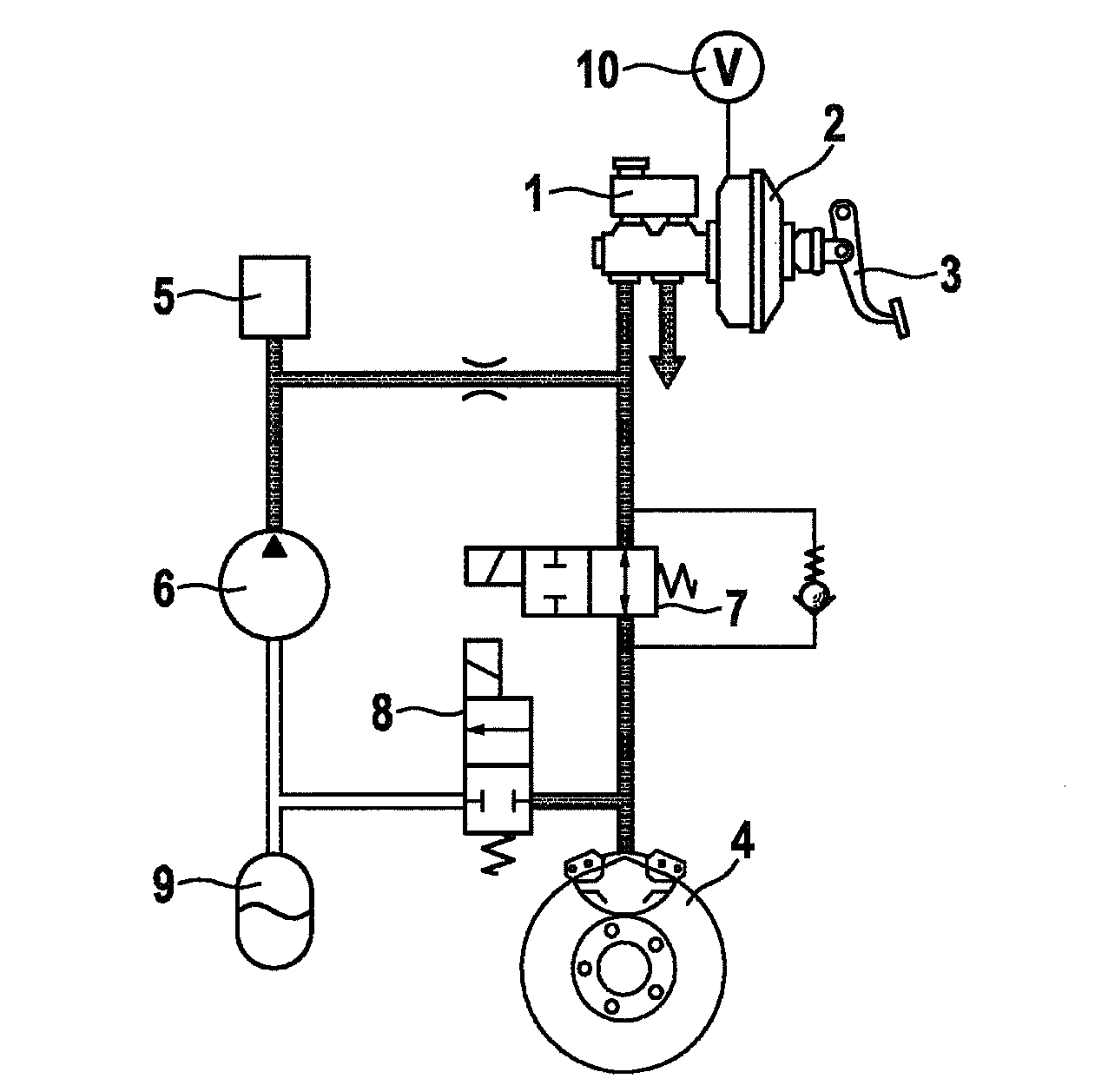
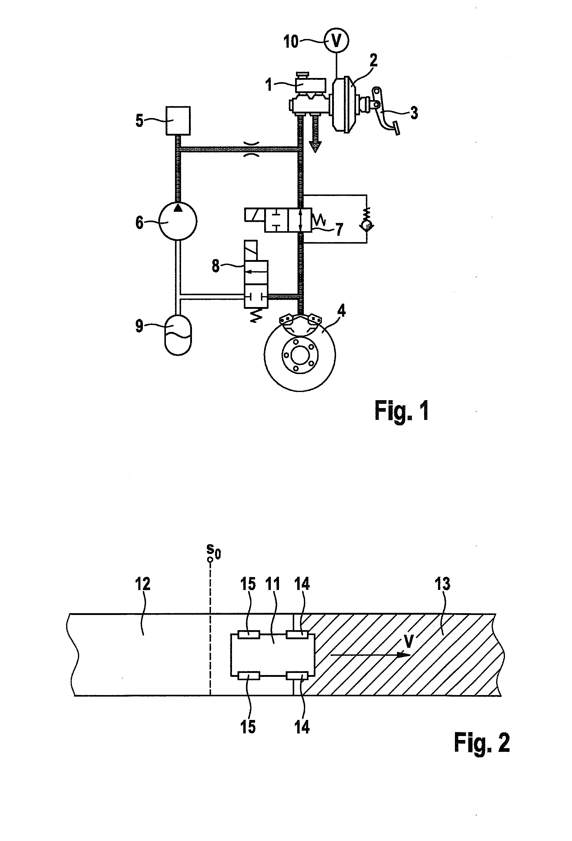
[0015]FIG. 1 shows a typical brake circuit of a hydraulic braking system having an ABS function. This brake circuit includes a brake master cylinder 1 having a container for the hydraulic fluid situated thereon. A brake booster 2 is coupled to a brake pedal 3 and boosts the brake force applied by the driver.

[0016]The brake pressure generated in brake master cylinder 1 is guided to a wheel brake 4 via an inlet valve 7. An outlet valve 8 situated at the output of wheel brake 4 is closed in this state.

[0017]FIG. 2 shows a vehicle 11 which drives at a speed v on a roadway having different friction coefficients. The roadway has an area 12 having a relatively high friction coefficient μ, such as asphalt, and an area 13 having a relatively small friction coefficient μ, such as snow or ice. Vehicle 11 is in a braking operation which has started in place s0.

[0018]In the illustrated position, front wheels 14 of vehicle 11 are directly at the transition between area 12 having the high friction...


PUM


Abstract

A brake device is described for braking the wheels of a vehicle. The brake device includes at least one brake master cylinder, a brake booster, a wheel brake, a return pump, using which a hydraulic fluid may be pumped back from the wheel brake in the direction of brake master cylinder. A sensor system for detecting an abrupt negative change in the friction coefficient of the roadway is provided. An arrangement is provided according to which the boost of the brake booster is set to a smaller value if a braking maneuver has been detected on a roadway having an abrupt negative change in the friction coefficient than in the case of a braking maneuver on a roadway without an abrupt negative change in the friction coefficient.

Description

FIELD OF THE INVENTION[0001]The present invention relates to a braking system for a vehicle having an improved braking characteristic in a driving situation in which the vehicle brakes on a roadway having an abrupt negative change in the friction coefficient, as well as a method for braking a vehicle in a corresponding driving situation.BACKGROUND INFORMATION[0002]Various brake control systems, such as ABS, ASR, or ESP, are known from the related art, using which the wheels may be prevented from blocking during the braking action. These systems generally monitor the wheel slip with the aid of the wheel speed sensors. If the brake control system detects an excessively high wheel slip on a wheel, the brake pressure is temporarily reduced in the associated wheel brake. For this purpose, an outlet valve is usually opened. The brake fluid present in the wheel brake then flows through the outlet valve into a storage chamber and is conveyed from there back in the direction of the brake mas...

Claims


Application Information

Patent Timeline
IPC IPC(8): B60T8/1763
CPCB60T8/172B60T8/3265B60T8/4275B60T8/448B60T8/1763B60T13/686B60T13/72B60T2210/124B60T13/146
Inventor BRUEGGEMANN, RAINERREIZE, ANDREASFRUEH, PHILLIP
Owner ROBERT BOSCH GMBH
Learn More