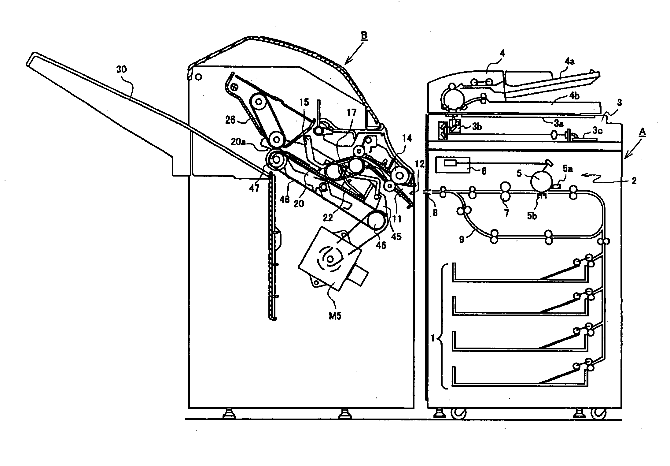
Method of sheet alignment and method of post-processing comprising the same and method of image formation

a sheet alignment and post-processing technology, applied in the direction of electrographic process, instruments, transportation and packaging, etc., can solve the problems of inconvenient post-processing, sheet inclination on the tray, and disadvantageous rotation of the sheet, so as to reduce the conveying force applied to the sheet by the sheet transfer device and increase the effect of conveying for

Active Publication Date: 2011-05-05
NISCA KK
View PDF3 Cites 2 Cited by
  • Summary
  • Abstract
  • Description
  • Claims
  • Application Information

AI Technical Summary

Benefits of technology

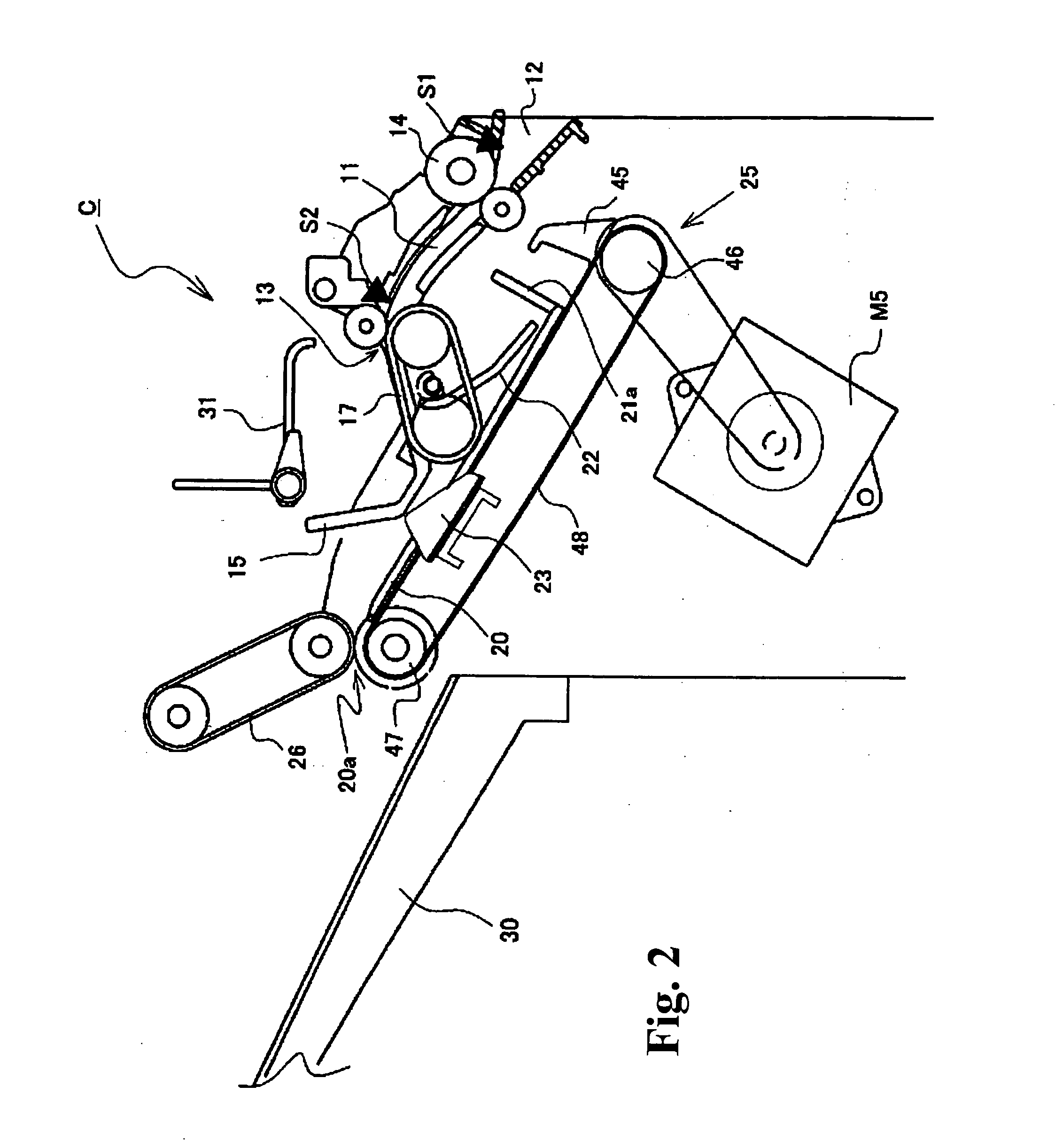
[0017]The sheet transfer device is configured to be able to adjust a conveying force applied to the sheet on the tray device. The control device is configured so that (1) when the sheet on the tray device abuts against the sheet end regulating device, the conveying force applied to the sheet by the sheet transfer device is reduced and (2) after the sheet abuts against the sheet end regulating device and when the widthwise aligning device places the sheet at the appropriate position in the width direction, the conveying force applied to the sheet by the sheet transfer device is increased.

Problems solved by technology

Thus, when the sheet is placed at the appropriate position in the width direction, a rotating force may disadvantageously act on the sheet as a result of the relationship between a sheet centroid position, varying with the sheet size, and a sheet widthwise aligning position set by the aligning device.
As a result, the aligning operation may result the sheets inclined on the tray (skew state) .
As a result, the sheet is rotated as shown in the figure and thus placed in an incorrect position, resulting in an inappropriate post-process.
Such a misaligned sheet causes an inappropriate post-process, for example, a stapling process.

Method used


Image

  • Method of sheet alignment and method of post-processing comprising the same and method of image formation
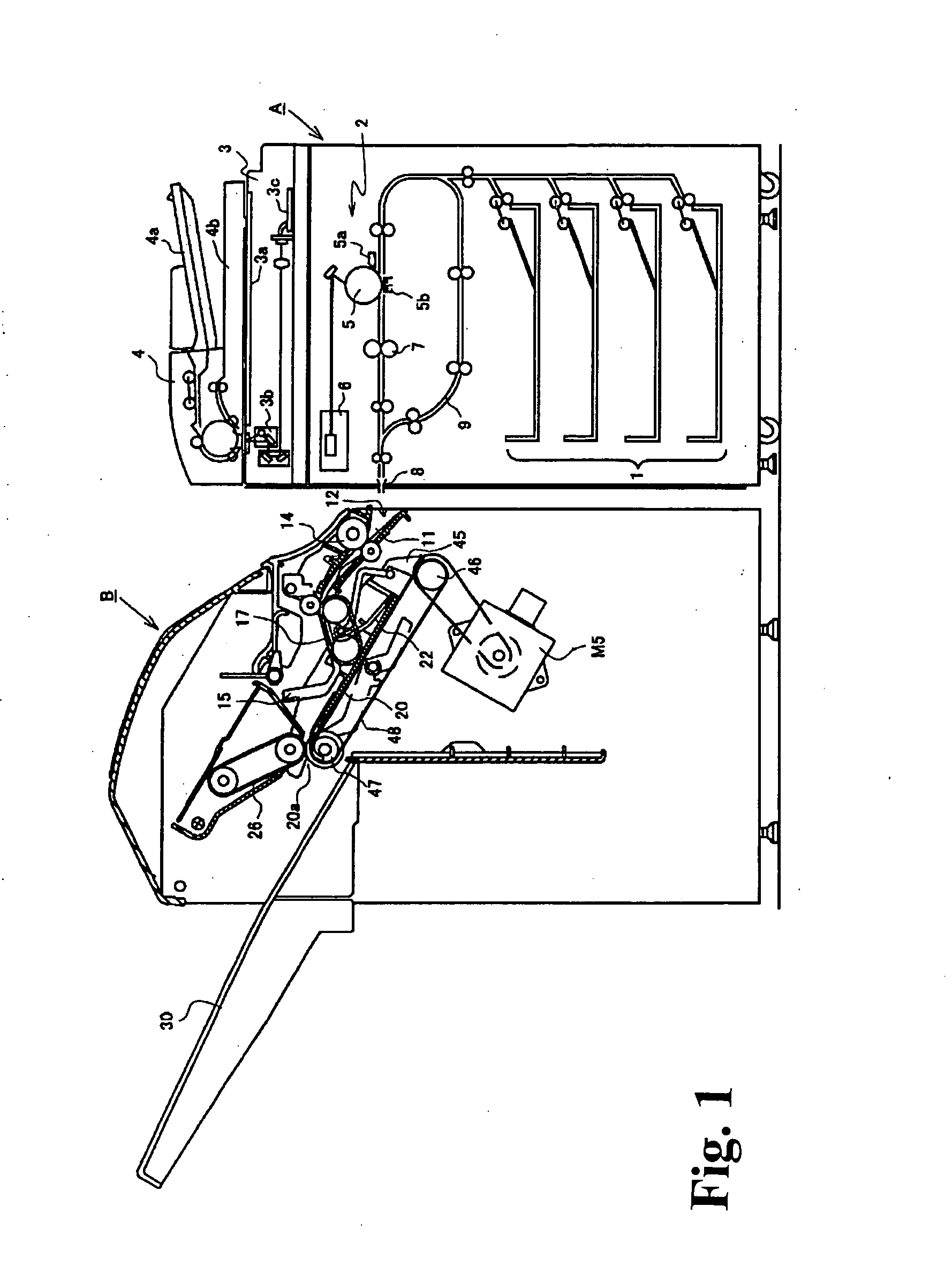
  • Method of sheet alignment and method of post-processing comprising the same and method of image formation
  • Method of sheet alignment and method of post-processing comprising the same and method of image formation

Examples


second embodiment

[Second Embodiment]

[0064]A second embodiment different from the first embodiment described above will be described with reference to FIGS. 9(a)-9(c). In the first embodiment, the conveying force exerted on the sheet is adjusted by varying the speed of the sheet feeding rotating member 17 in order of the “high speed rotation”, the “low speed rotation”, and the “high speed rotation”. However, with the speed of the sheet feeding rotating member 17 set at a fixed value, a brake device (for example, the paddle 31, described below) may be used to adjust the moving speed of the sheet. In the second embodiment, shown in FIGS. 9(a)-9(c), the paddle 31 is used as a brake device for acting on the sheet to reduce the moving speed of the sheet. The other arrangements are the same as those in FIGS. 3(a) and 3(b) and are denoted by the same reference numerals. The other arrangements will not be described below.

[0065]The driving motor M6 for the paddle 31 is composed of a forward and backward rotat...

third embodiment

[Third Embodiment]

[0067]Now, an embodiment different from the above first and second embodiments will be described on the basis of FIGS. 10(a) to 11(b) In each of the above embodiments, the conveying force applied to the sheet is adjusted by varying the conveying speed. However, the conveying force can be adjusted by varying the pressure contact force between the sheet feeding rotating member 17 and the sheet. In the embodiment shown in FIGS. 10(a) and 10(b), the sheet feeding rotating member 17 is similar to that described above; the fixed pulley 16a is fixed to the apparatus frame, the movable pulley 16b is supported by the swinging arm member 19 borne by the rotating shaft 16c of the fixed pulley 16a, and the caterpillar belt 18 extends between the pulleys 16a and 16b. The driving motor M1 is coupled to the rotating shaft 16c. The sheet feeding rotating member 17 thus configured as described in the above embodiments has a weight member 41 that adjusts the pressure contact force e...


PUM

PropertyMeasurementUnit
speedaaaaaaaaaa
speedaaaaaaaaaa
sheet alignmentaaaaaaaaaa

Abstract

A method of a sheet alignment includes carrying a sheet from a sheet discharging port; transferring the sheet on a tray device toward a sheet end regulating device; moving the sheet on the tray device in a width direction orthogonal to the sheet discharging direction for widthwise alignment; and abutting again the sheet on the tray device against the sheet end regulating device while the sheet is in the widthwise alignment. When the sheet on the tray device is transferred toward the sheet end regulating device, the sheet is transferred at a predetermined speed. Before the sheet abuts against the sheet end regulating device, the speed is reduced to provide a conveying force to the sheet without stopping. While the conveying force is continuously applied to the sheet, the sheet is aligned in the width direction to thereby prevent skewing of the sheet relative to the sheet end regulating device.

Description

CROSS-REFERENCE TO RELATED APPLICATIONS[0001]The present application is a continuation application of U.S. Ser. No. 11 / 896,692 filed on Sep. 5, 2007. The application claims priority to Japanese patent application number 2006-257524 filed on Sep. 22, 2006, which is incorporated by reference in its entirety.”BACKGROUND OF THE INVENTION AND RELATED ART STATEMENT[0002]The present invention relates to a method of a post-processing receiving a sheet with an image formed thereon by a method of image formation using such as a copier or a printing machine, executing a post-process such as stapling, punching, or stamping on the sheet, and a method of sheet alignment placing the sheet at the post-process position in a predetermined posture.[0003]In general, sheet aligning devices of this kind are widely known to place sheets with images formed thereon by an image forming apparatus, on a tray in a predetermined posture for alignment, to execute a post-process such as stapling, stamping, or punc...

Claims


Application Information

Patent Timeline
Patent Type & Authority Applications(United States)
IPC IPC(8): G03G15/00
CPCB42C1/12B65H9/101B65H2801/31B65H2801/27B65H2515/30B65H2513/51B65H2301/4213B65H31/36B65H2220/15B65H2220/01B65H2220/02B65H2220/11
Inventor KUBO, EIICHIHOSAKA, MASATO
Owner NISCA KK
Why Eureka
Try Eureka