Water pouring device for electroplating travelling crane

A technology for electroplating cranes and electroplating tanks, applied in the direction of electrolysis process, electrolysis components, etc., can solve the problems of affecting the electroplating quality of the workpiece to be plated, the quality of the workpiece is not high, and mutual pollution, so as to avoid mutual pollution of the electroplating solution and improve the quality of electroplating Effect

Inactive Publication Date: 2012-07-25
JIANGSU HONGLIAN ENVIRONMENTAL PROTECTION TECH CO LTD
View PDF0 Cites 0 Cited by
  • Summary
  • Abstract
  • Description
  • Claims
  • Application Information

AI Technical Summary

Problems solved by technology

Since this pouring method is a differential pouring method, it can only solve the problem of pouring water in the left and right directions, and the water in the front and rear directions cannot be poured out.
The workpiece still has the electroplating solution of the previous process, which makes the electroplating solution of the previous process and the electroplating solution of the next process pollute each other, thus affecting the electroplating quality of the workpiece to be plated, making the quality of the electroplated workpiece not high

Method used


Image

  • Water pouring device for electroplating travelling crane
  • Water pouring device for electroplating travelling crane
  • Water pouring device for electroplating travelling crane

Examples


Embodiment Construction

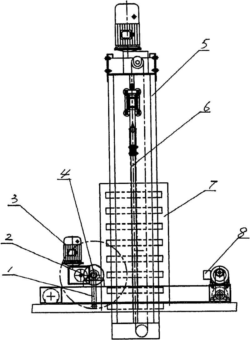
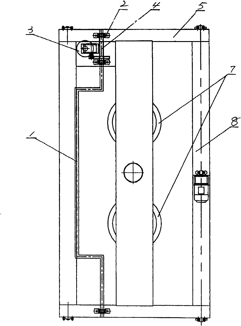
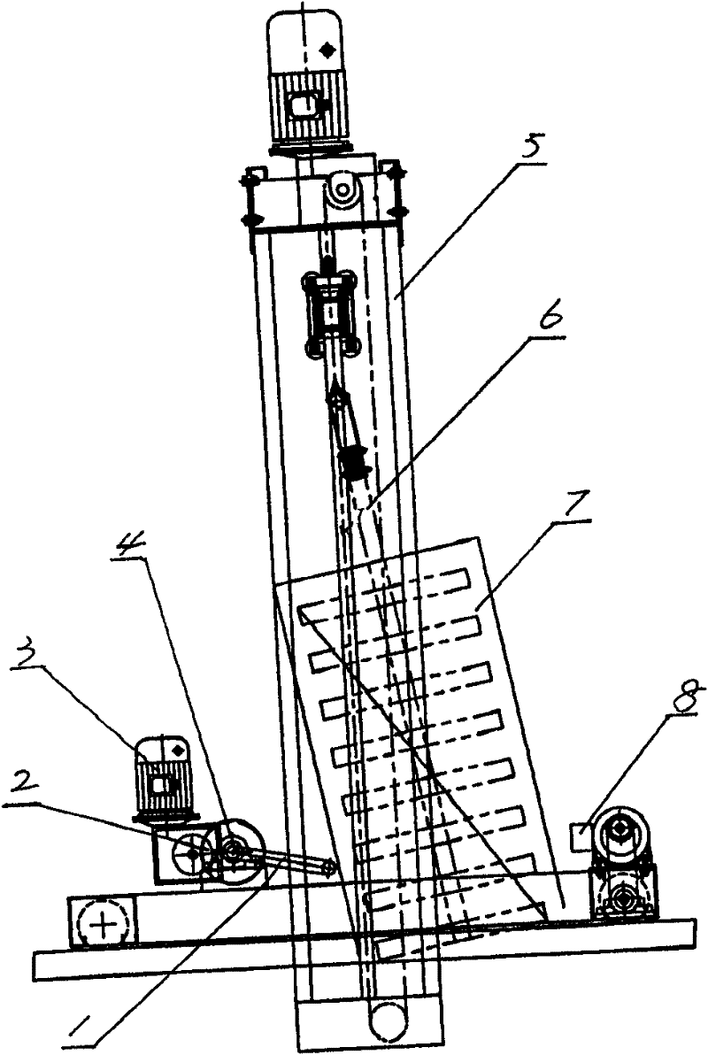
[0011] Such as figure 1 and figure 2 As shown, the electroplating vehicle pouring device of the present invention includes a door frame 5, which is installed on the electroplating tank. The door frame 5 is provided with a fixture 7 for placing the workpiece to be plated. There are two clamps 7, both of which are basket-type clamps, and they are suspended on the top beam of the door frame 5 by means of hangers 6. The top of the hanger 6 is hinged with the top of the door frame 5, and the hanger 6 can swing in the door frame 5 along its hinge point with the door frame 5, see image 3 . There are shaft seats 2 on the same side of the two vertical walls of the door frame 5, and there are coaxial shaft holes on the two shaft seats. There is a connecting rod 4 between the two shaft seats 2, and the two ends of the connecting rod 4 are respectively rotatable and inserted into the corresponding A power mechanism 3 is connected to one end of the connecting rod 4 in the shaft hole ...


PUM


Abstract

The invention relates to a water pouring device for an electroplating travelling crane. The water pouring device comprises a gantry, wherein the gantry is positioned on an electroplating bath; and a jig for accommodating a workpiece to be plated is arranged in the gantry, and is suspended on a top beam of the gantry through a suspension bracket. The water pouring device is characterized in that: the top of the suspension bracket is hinged with the top of the gantry, and can swing in the gantry along a hinge point between the suspension bracket and the gantry; two vertical walls of the gantry are provided with axle seats on the same side; the two axle seats are provided with coaxial axle holes; a connecting rod is arranged between the two axle seats; the two ends of the connecting rod are rotationally inserted into the axle holes on corresponding axle seats respectively; and one end of the connecting rod is connected with a power mechanism. The middle of the connecting rod is provided with a U-shaped bent section, so that the U-shaped bent section is discontinuously contacted with the jig in the rotating process of the connecting rod. Due to the adopting of the water pouring devicefor the electroplating travelling crane, the electroplating quality of the plated workpiece can be enhanced. The water pouring device is suitable for pouring electroplate liquid remained in the plated workpiece out when the jig accommodating the plated workpiece is lifted from the electroplating bath in the electroplating industry.

Description

technical field [0001] The invention relates to an electroplating crane. Specifically, it is a pouring device used to pour out the electroplating solution remaining in the workpiece to be plated when the jig with the workpiece to be plated is lifted from the electroplating tank. Background technique [0002] It is known in the electroplating industry that a door frame is provided on the electroplating tank in the electroplating workshop of the electroplating factory, and the door frame is provided with a fixture for placing the workpiece to be plated. When an electroplating process is completed, it is necessary to lift the workpiece to be plated from the electroplating tank by means of a fixture and move it into the electroplating tank of the next process. Due to the different shapes of the workpiece to be plated, the surface is uneven. When the jig with the workpiece to be plated is lifted from the electroplating tank of the previous process, it is inevitable that the pla...

Claims


Application Information

Patent Timeline
Patent Type & Authority Patents(China)
IPC IPC(8): C25D17/00
Inventor 吴欲李海军
Owner JIANGSU HONGLIAN ENVIRONMENTAL PROTECTION TECH CO LTD
Why Eureka
Try Eureka