Structure of electroplating rotary drum

An electroplating drum and structure technology, which is applied in the direction of electrolysis process, electrolysis components, etc., can solve the problems of increased manufacturing cost, poor water permeability of electroplating drum, time-consuming and labor-intensive, etc.

Inactive Publication Date: 2009-07-22
HURMG YIEH MACHINERY IND
View PDF0 Cites 7 Cited by
  • Summary
  • Abstract
  • Description
  • Claims
  • Application Information

AI Technical Summary

Problems solved by technology

[0003] 1. The overall strength of the electroplating barrel is insufficient: the body of the existing electroplating barrel is firstly drilled with a large number of through holes on the plate and then heated and bent to shape. However, after research, it is found that even if the number of through holes passes through Careful calculation, but it is an unavoidable problem that the barrel body strength of the electroplating barrel will be damaged after drilling holes on the plate. Therefore, when the electroplating barrel contains heavy electroplated objects and is used alternately with hot and cold plating solutions after continuous rotation , it is very easy to cause the deformation of the electroplating drum, and even the accident of the drum body breaking in severe cases
[0004] 2. The manufacturing cost of the electroplating barrel is too high: the through-holes on the body of the existing electroplating barrel are drilled one by one by machinery, and the subsequent manual bending and forming can only be performed after the through-holes are covered with the entire plate. The entire drilling, Bending and forming operations are extremely time-consuming and labor-intensive, and the processing speed is extremely slow, which not only causes time-consuming and labor-intensive problems, but also leads to a relatively high manufacturing cost
[00

Method used


Image

  • Structure of electroplating rotary drum
  • Structure of electroplating rotary drum
  • Structure of electroplating rotary drum

Examples


Embodiment Construction

[0024] The above and other technical features and advantages of the present invention will be described in more detail below with reference to the accompanying drawings.

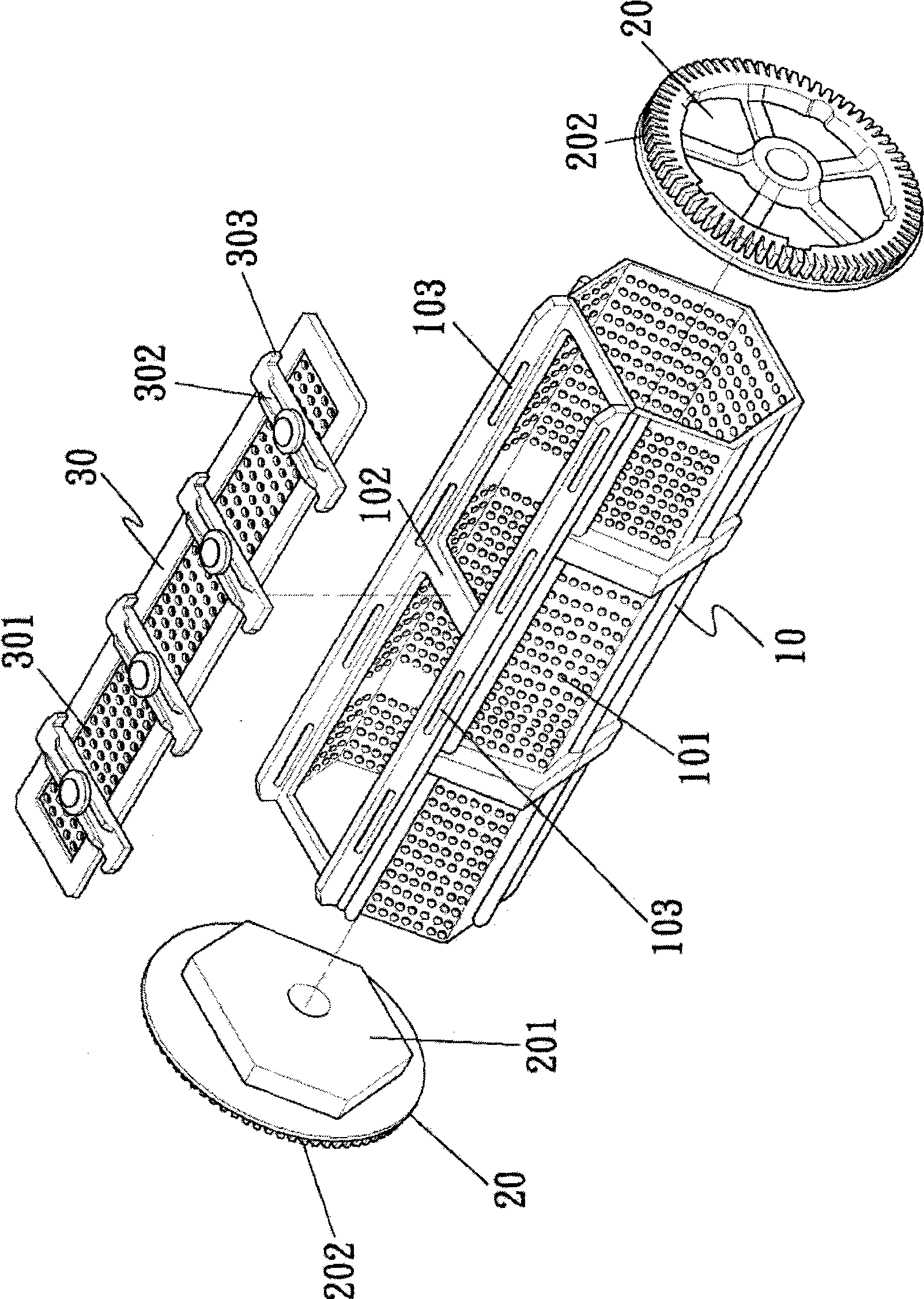
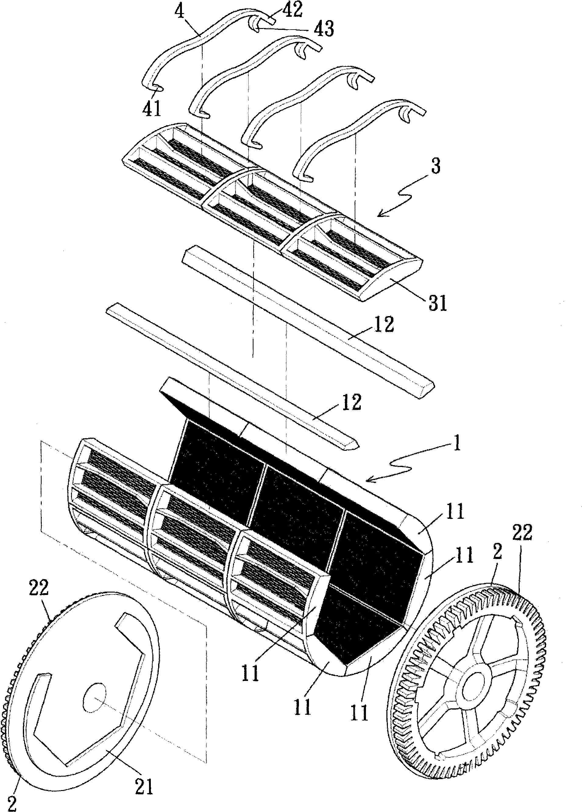
[0025] First see figure 2 Schematic diagram of the three-dimensional decomposition of the electroplating drum, image 3 The three-dimensional exploded schematic diagram of the barrel body part of the electroplating drum, Figure 4 The exploded schematic diagram of the rectangular plate shown in Fig. 5 is combined with the three-dimensional schematic diagram, plan view and cross-sectional schematic diagram of the plate unit from different angles in Figs. 5 to 8; the present invention mainly provides a kind of figure 2 The shown electroplating drum structure mainly includes a barrel body 1, a round sealing plate 2 on both sides, an upper cover 3 and a plurality of upper cover pressure strips 4, wherein:

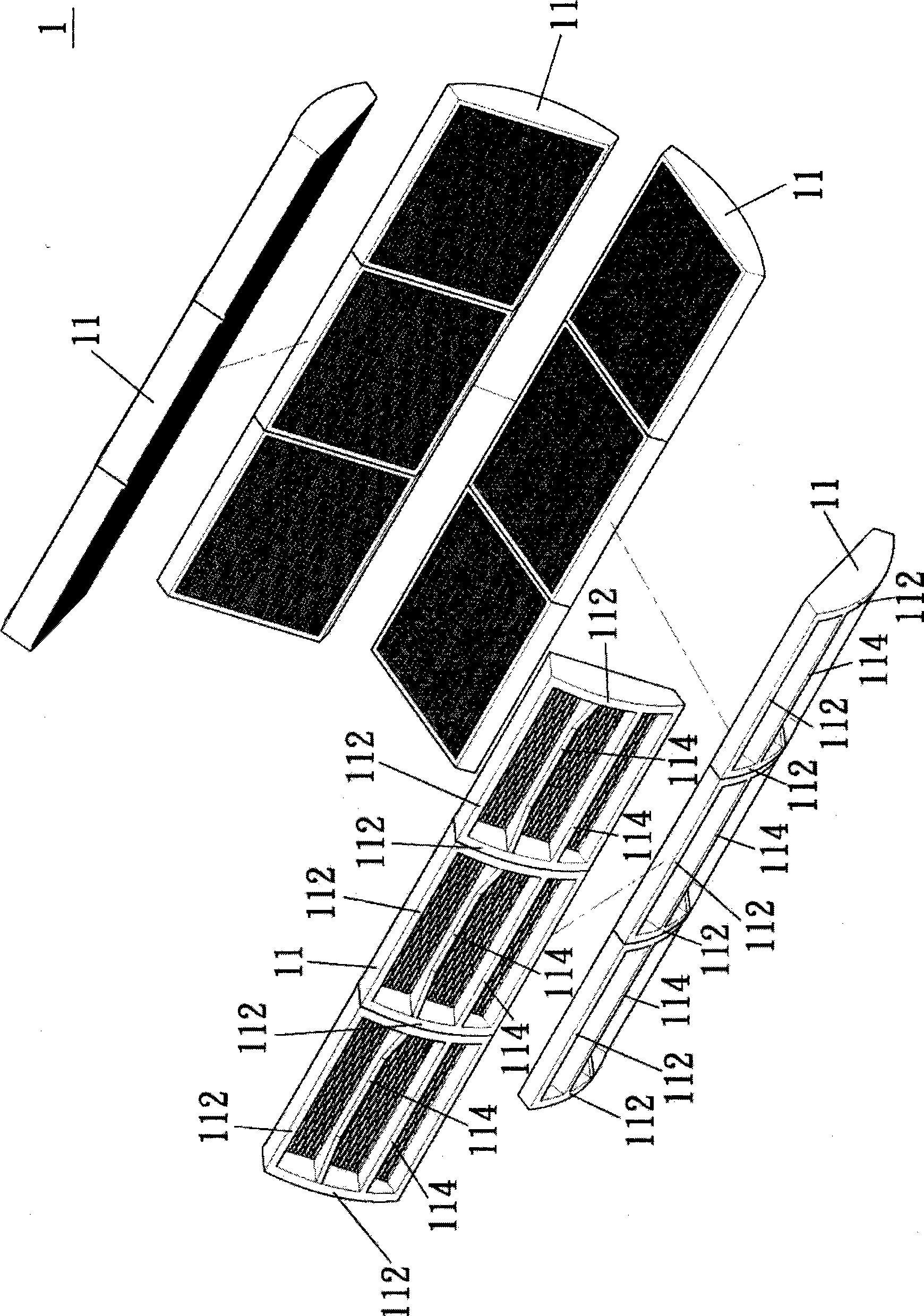
[0026] The barrel body 1, the barrel body 1 is composed of multiple plastic rectangular plates 11 over...


PUM


Abstract

The invention provides a structure of an electroplating rolling barrel, comprising a barrel body, a round sealing plate, an upper cover and a plurality of upper cover pressing bars; the barrel body is a polygonal barrel-shaped container which is provided with an opening and formed by the overlapping connection and combination of a plurality of rectangular plates one by one; the rectangular plates are respectively provided with a slab which is provided with a plurality of through holes; the upper cover is a rectangular plate; the rectangular plate is provided with a slab which is provided with the through holes; two ends of the upper cover pressing bar are respectively provided with a hooking end and a pulling handle end; the pulling handle end also integrally extends by a clamping end corresponding to the hooking end; the hooking end and the clamping end are respectively used for hooking two sides of the opening of the barrel body; the upper cover is pressed on the barrel body so as to close the opening; and the structure of the electroplating rolling barrel has the advantages and characteristics of simplifying the preparation process of the electroplating rolling barrel, reducing the preparation cost, improving the whole strength of the electroplating rolling barrel and improving the electroplating quality.

Description

technical field [0001] The invention relates to a structure of an electroplating drum, in particular to a method of separately manufacturing a large number of plate units by injection molding, then connecting the plate units laterally to form a rectangular plate, and finally connecting all the plates to each other. Combined with forming a polygonal electroplating drum with an opening, it mainly has the advantages and characteristics of simplifying the manufacturing process of the electroplating drum, reducing the manufacturing cost, improving the overall strength of the electroplating drum and improving the electroplating quality. Background technique [0002] Overview of the structure of the existing electroplating drum figure 1 As shown, it mainly includes a barrel body 10, round sealing plates 20 on both sides and an upper cover 30, wherein, in terms of the structure and processing of the barrel body 10, usually first on a large flat plastic sheet, according to the calcul...

Claims


Application Information

Patent Timeline
IPC IPC(8): C25D17/20
Inventor 阮连庆
Owner HURMG YIEH MACHINERY IND
Why Eureka
Try Eureka