Method and device for galvanising substrates and solar cells

A technology of solar cells and electrolytic plating, applied in the direction of circuits, electrolytic components, electrical components, etc., can solve the problems of infeasibility in mass production and utilization, and achieve the effects of improving plating quality, increasing deposition speed, and increasing output

Inactive Publication Date: 2012-05-16
SCHOTT SOLAR AG (DE)
View PDF4 Cites 8 Cited by
  • Summary
  • Abstract
  • Description
  • Claims
  • Application Information

AI Technical Summary

Problems solved by technology

Mass production utilizing this device is not feasible

Method used


Image

  • Method and device for galvanising substrates and solar cells
  • Method and device for galvanising substrates and solar cells
  • Method and device for galvanising substrates and solar cells

Examples


Embodiment Construction

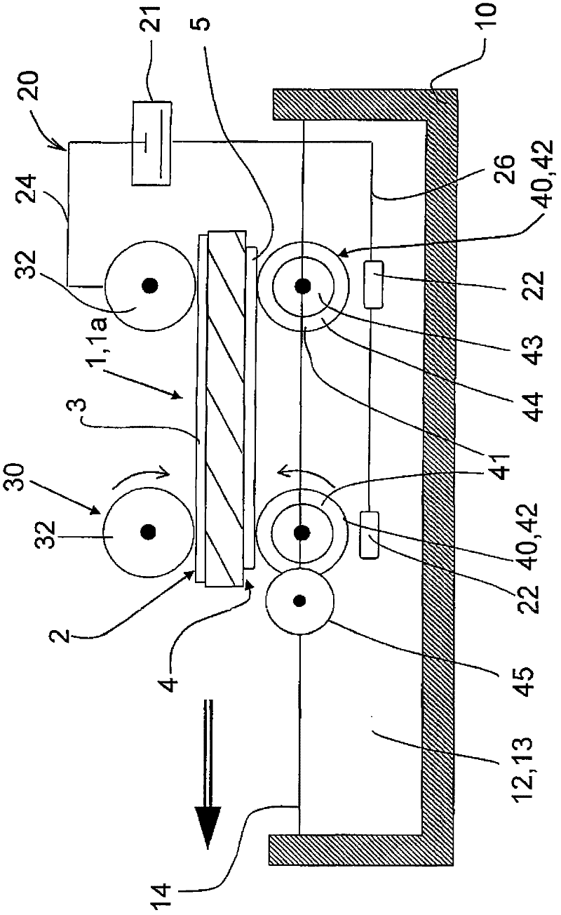
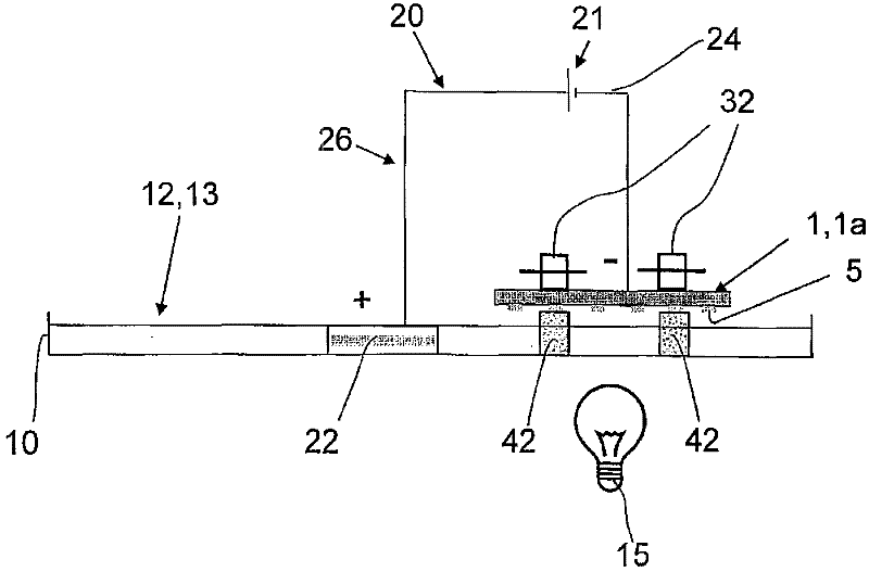
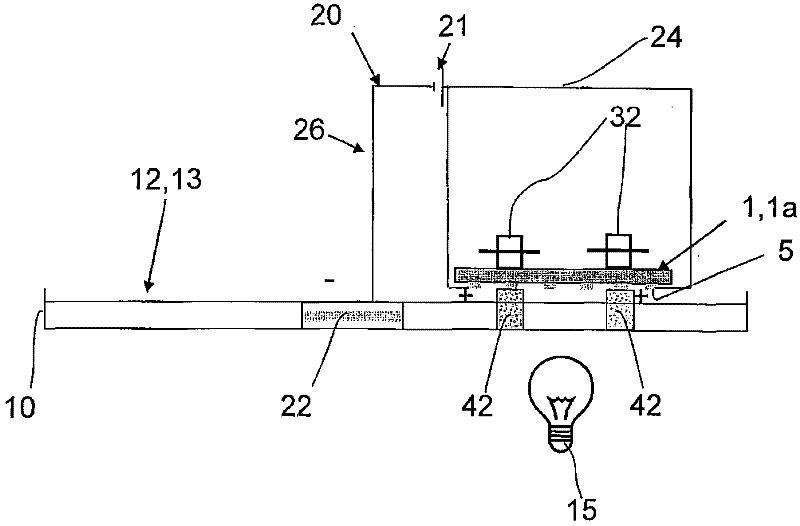
[0062] exist figure 1 A device for electroplating a substrate 1 is shown in , comprising a liquid reservoir 12 in the form of a plating tank 10 in which an electrolytic plating liquid 13 is located. In this embodiment, the substrate 1 is a solar cell 1a.

[0063] The substrate 1 is arranged between the upper transfer device 30 and the lower transfer device 40, and moves in the direction of the arrow. The two transfer devices 30 , 40 are arranged in such a way that the substrate 1 is located above the coating bath 10 which is open towards the top. The upper conveyor 30 has upper conveyor rollers 32, only two of which are drawn. The substrate 1 has a metallization 3 on the back side 2 which is contacted by a roller 32 on the upper right, which is connected via an electrical connection 24 to the negative pole of the power supply 21 . The positive pole of the power supply 21 is connected via an electrical connection line 26 to an electrode 22 which forms the anode and which is ...


PUM

PropertyMeasurementUnit
densityaaaaaaaaaa
tensile strengthaaaaaaaaaa
transmittivityaaaaaaaaaa

Abstract

The present invention provides a method and a device for galvanising substrates and solar cells. The device comprises a reservoir (12) having an electrolytic coating liquid (13), a lower transport device (40), and an upper transport device (30) for substrates (1), where a transport device comprises mechanisms (20,21,24,32) for contacting and connecting the substrates (1) to a voltage source (21). At least one transport device (30) is provided with at least one tampon (41) which is made of a absorbent material (44). Furthermore, the mechanisms are equipped so the tampon (41) absorbs the electrolytic coating liquid (13) and contacts with the surfaces of the substrates (1) to be plated.

Description

technical field [0001] The invention relates to a device for the galvanic coating of substrates according to the preamble of claim 1 . [0002] The invention likewise relates to a method for the galvanic coating of substrates and solar cells according to claims 9 and 10 . Background technique [0003] From DE 10 2005 038 449 A1 a device is known for the galvanic coating of substrates, in particular solar cells, in which device the solar cells are guided between an upper conveyor roller and a lower conveyor roller Electrolyte bath. For the electrical contact connection, rollers are likewise provided, which come into contact with the substrate, or bear against it. Deposits likewise occur on the contact rollers, so that they have to be lifted from time to time, moved out of the electrolyte and the coating has to be removed from the contact rollers. With this method, plating can be performed on all surfaces. However, this method does not introduce a partial coating of the fr...

Claims


Application Information

Patent Timeline
Patent Type & Authority Applications(China)
IPC IPC(8): C25D7/12C25D17/28
CPCC25D5/028C25D5/006C25D17/00C25D17/005C25D7/12H01L21/2885C25D5/024C25D17/001C25D5/011
Inventor 洛塔尔·利珀特马库斯·卡泽达伊萨沙·赖梅
Owner SCHOTT SOLAR AG (DE)
Why Eureka
Try Eureka