Conducting ring, power supply device based on conducting ring and electroplating jig based on power supply device

A technology for power supply devices and electroplating fixtures, applied in current conduction devices, circuits, electrolysis processes, etc., can solve the problems of different wafer coating thicknesses, current density indexing deviations, etc., to ensure consistency and uniformity, reduce Frequency, the effect of reducing maintenance costs

Pending Publication Date: 2018-11-06
SHENZHEN CHENGGONG CHEM
View PDF6 Cites 8 Cited by
  • Summary
  • Abstract
  • Description
  • Claims
  • Application Information

AI Technical Summary

Problems solved by technology

However, in the actual electroplating process, it is very easy to have different coating thicknesses in different regions of the wafer. The main reason for the above problems is the deviation of the current density in each region. Therefore, how to ensure the current distribution density in each region of the wafer Consistency has become an urgent problem for technicians to solve

Method used


Image

  • Conducting ring, power supply device based on conducting ring and electroplating jig based on power supply device
  • Conducting ring, power supply device based on conducting ring and electroplating jig based on power supply device
  • Conducting ring, power supply device based on conducting ring and electroplating jig based on power supply device

Examples


Embodiment Construction

[0025] In order to express the present invention more clearly, the present invention will be further described below in conjunction with the accompanying drawings.

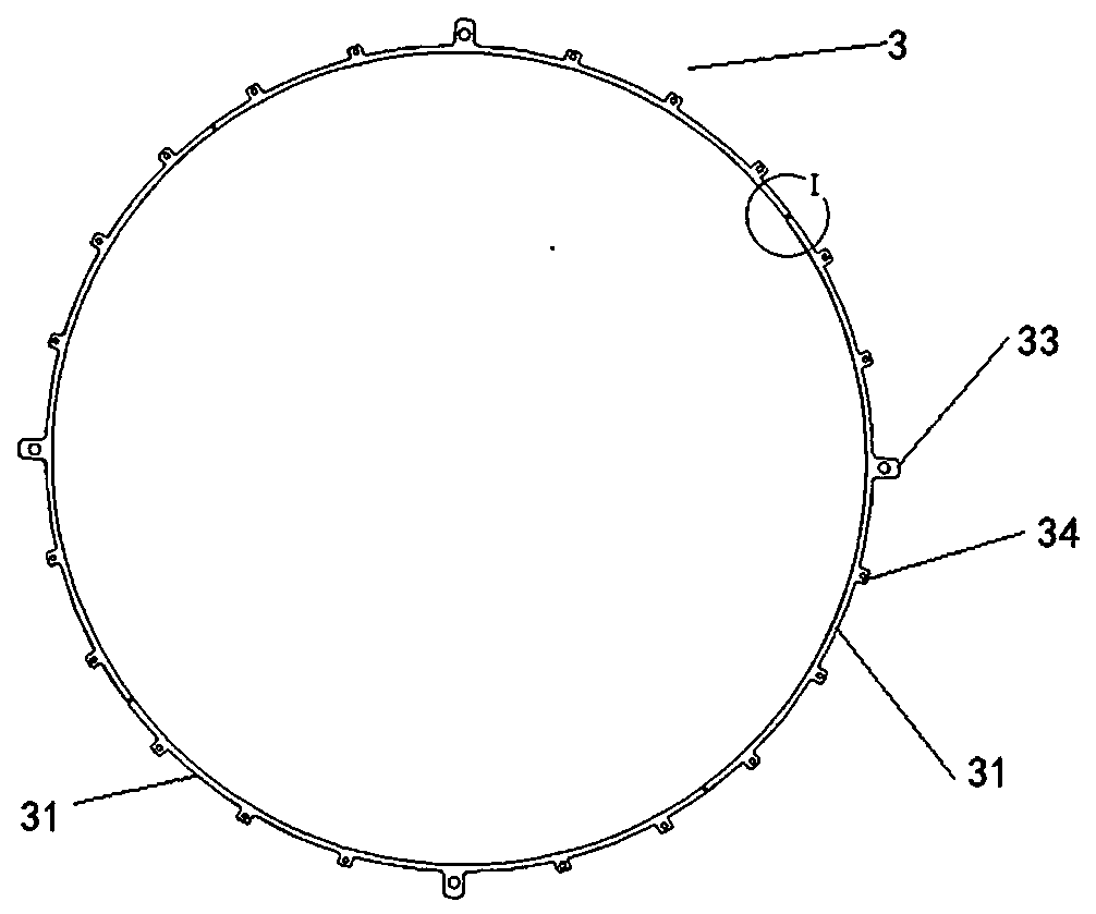
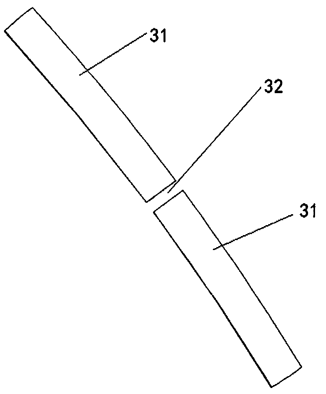
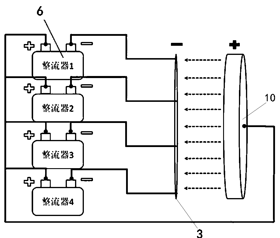
[0026] see Figure 1-2 , the conductive ring provided by the present invention includes a conductive ring body 3, the conductive ring body is distributed in a segmented structure, and is composed of a plurality of conductive segments 31; the opening 32 between every two adjacent conductive segments is filled The insulating glue is separated by the insulating glue layer; the surface of the conductive ring body is wrapped with an insulating glue layer; and the conductive ring body is provided with at least one electrode 33 and at least one supporting foot 34 .

[0027] In this embodiment, the outer surface of the conductive ring body 31 is sequentially provided with a nickel-plated layer and a silver-plated layer from inside to outside, and the silver-plated layer is placed between the nickel-plated layer and the in...


PUM

PropertyMeasurementUnit
thicknessaaaaaaaaaa
thicknessaaaaaaaaaa
sizeaaaaaaaaaa

Abstract

The invention discloses a conducting ring, a power supply device based on the conducting ring and an electroplating jig based on the power supply device. The conducting ring comprises a conducting ring body. The conducting ring body is distributed in a sectional type structure and is composed of a plurality of conducting sections. Every two adjacent conducting sections are isolated after a brokenopening between the two adjacent conducting sections is filled with insulation paste. The surface of the conducting ring body is wrapped with an insulation paste layer. The conducting ring body is provided with at least one electrode and at least one supporting leg. The conducting ring is evenly divided into the multiple sections, each section can independently carry out current control, so that the consistence and the uniformity of current distribution density of a wafer or a whole printed circuit board are ensured, and the quality of a surface electroplating layer of the conducting ring is guaranteed; and a traditional conducting ring body is additionally provided with a nickel-plated layer and a silver-plated layer, the conducing impedance is reduced, the stability of transmitting currents of conducting ring is enhanced, the frequency of repairing and changing the conducting ring body is reduced, and the repairing cost is reduced.

Description

technical field [0001] The invention relates to the technical field of electroplating, in particular to a conductive ring, a power supply device based on the same, and an electroplating fixture based on the power supply device. Background technique [0002] In the production process of semiconductor components (such as wafers or printed circuit boards, etc.), the surface needs to be electroplated. Taking the wafer as an example, it needs to be placed on the electroplating fixture. The wafer electroplating fixture is equipped with Conductive rings, these conductive rings are in contact with the wafers on the wafer plating fixture, therefore, the wafers on the wafer plating fixture can be connected to an external power source during the electroplating process, and then can be deposited on its surface through the decomposition of the electroplating solution Form the desired coating. However, in the actual electroplating process, it is very easy to have different coating thickn...

Claims


Application Information

Patent Timeline
Patent Type & Authority Applications(China)
IPC IPC(8): C25D17/06C25D17/00C25D7/12
CPCC25D7/12C25D17/00C25D17/001C25D17/007C25D17/06
Inventor 姚吉豪何志刚
Owner SHENZHEN CHENGGONG CHEM
Why Eureka
Try Eureka