
Pulley stroke beam type pumping unit

A beam-type pumping unit and pulley technology, which is applied to liquid variable-capacity machinery, mechanical equipment, machines/engines, etc., can solve the problems of inconvenient operation, high energy consumption, short stroke, etc., and achieve reasonable structure and reduce production. The effect of running energy consumption and high reliability

Active Publication Date: 2012-11-07
高林
View PDF0 Cites 0 Cited by
  • Summary
  • Abstract
  • Description
  • Claims
  • Application Information

AI Technical Summary

Problems solved by technology

[0003] The present invention provides a pulley-extended beam pumping unit, which overcomes the shortcomings of the prior art and can effectively solve the problems of short stroke, small displacement, high energy consumption and inconvenient operation of the existing beam pumping unit. question

Method used


Image

  • Pulley stroke beam type pumping unit
  • Pulley stroke beam type pumping unit
  • Pulley stroke beam type pumping unit

Examples


Embodiment 1

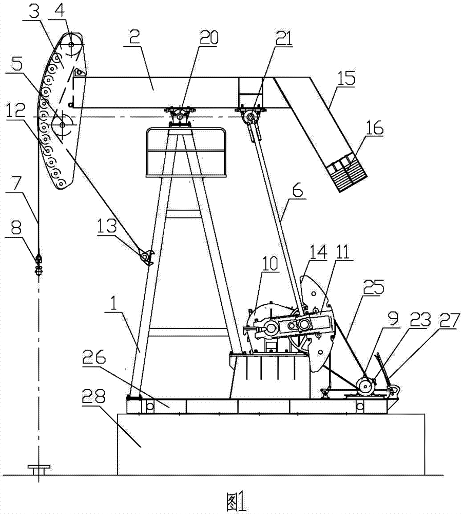
[0027] Embodiment 1: as attached Figure 5 As shown, the counterweight device is a counterweight 14 as required, and the counterweight 14 is installed on the crank 11 .

Embodiment 2

[0028] Embodiment 2: as attached Figure 6 Shown, as required, counterweight device is counterweight box 15, and the upper end of counterweight box 15 is installed on the right-hand member of traveling beam 2, and the lower end of counterweight box 15 is fixedly equipped with movable counterweight block 16.

Embodiment 3

[0029] Embodiment 3: as attached figure 1 As shown, as required, the counterweight device is a counterweight 14 and a counterweight box 15, the counterweight 14 is installed on the crank 11, the upper end of the counterweight box 15 is installed on the right end of the beam 2, and the lower end of the counterweight box 15 is fixedly installed with a movable Counterweight 16.

[0030] According to actual needs, the above pulley extended-range beam pumping unit can be further optimized or / and improved:

[0031] as attached Figures 1 to 6 As shown, in order to facilitate installation and disassembly, the left end of the beam 2 is fixed with a hanging seat 17, and a fixed connecting body 18 is arranged on the inner side of the upper part of the donkey head 3. A supporting body 19 capable of leaning against the left end surface of the beam 2 is fixed.

[0032] as attached Figures 1 to 6 As shown, as required, the middle part of the beam 2 is hinged on the top of the frame 1 t...


PUM


Abstract

The invention relates to a beam pumping unit, and in particular relates to a pulley stroke-lengthening beam pumping unit which comprises a frame, a walking beam, a horse head, an upper movable pulley, a lower movable pulley, a crossbeam connecting rod, a load bearing belt, a belt hanger, a motor, a speed reducer and a crank, wherein a transmission device is mounted between a power output shaft ofthe motor and a power input shaft of the speed reducer; the crank is mounted on a power output shaft of the speed reducer; the middle of the walking beam capable of swinging up and down is hinged at the top of the frame; the upper end of the crossbeam connecting rod is hinged on the right part of the walking beam; and the lower end of the crossbeam connecting rod is hinged on the crank. The pulley stroke-lengthening beam pumping unit provided by the invention is of a reasonable and compact structure and convenient to use, can realize long stroke on a relatively small mechanical structure through the upper movable pulley and the lower movable pulley, meets the need for large-displacement oil production, has high reliability, saves the raw materials for manufacturing a pumping unit, reducesenergy consumption of production, regulates balance, ensures safe, convenient and quick operation, and can be used as a conventional stroke pumping unit by replacing the horse head or load bearing belt.

Description

technical field [0001] The invention relates to a beam pumping unit, which is a pulley-extended beam pumping unit. Background technique [0002] The beam pumping unit is the main equipment for oil production, and generally includes a rope hanger, a donkey head, a beam, a frame, a connecting rod beam, a reducer, a crank, a counterweight, a belt, an electric motor, a base and a foundation; The following disadvantages: short stroke, small displacement, high energy consumption, inconvenient operation, especially not suitable for the exploitation of heavy oil. Contents of the invention [0003] The present invention provides a pulley-extended beam pumping unit, which overcomes the shortcomings of the prior art and can effectively solve the problems of short stroke, small displacement, high energy consumption and inconvenient operation of the existing beam pumping unit. question. [0004] The technical solution of the present invention is achieved through the following measure...

Claims


Application Information

Patent Timeline
Patent Type & Authority Patents(China)
IPC IPC(8): E21B43/00F04B47/14
Inventor 高林于晓石一迪张睿强
Owner 高林
Learn More