
Heat dissipation silicone oil clutch

A silicone oil clutch, heat dissipation technology, applied in clutches, fluid clutches, machines/engines, etc., can solve the problems of unable to meet the heat dissipation requirements of large torque clutches, reduce the reliability of silicone oil clutches, and reduce the kinetic energy efficiency of fans, etc., to save energy Making raw materials, eliminating the cost of porosity detection, and the effect of small thermal shock

Active Publication Date: 2022-03-18
DONGFENG BEHR THERMAL SYST
View PDF4 Cites 0 Cited by
  • Summary
  • Abstract
  • Description
  • Claims
  • Application Information

AI Technical Summary

Problems solved by technology

[0004] Since the fan is matched with the clutch and installed on the engine crankshaft or fan bracket, when the fan rotates, the torque kinetic energy output by the clutch cannot be completely converted into the consumption of the fan operation, and additional slip heat energy will inevitably be generated. If this part of energy cannot be Release in time, it will increase the clutch temperature additionally
An increase in the temperature of the clutch will cause the following problems: First, the high temperature will lead to the gradual deterioration of the silicone oil inside the clutch, the performance of the silicone oil will be attenuated, and the efficiency of converting the clutch torque into fan kinetic energy will become lower, thereby generating more slip heat energy and forming a vicious circle; It is transmitted to the key components such as the internal bearing and sealing ring of the clutch, causing high temperature failure and reducing the reliability of the silicone oil clutch; again, the high temperature will also be transmitted to the electronic control component - the electronic control solenoid, resulting in a reduction in the life of the solenoid even damaged
Due to the limitations of the liquid die-casting process, the density of heat dissipation fins on the front and rear covers and the height of the fins are limited, which cannot meet the heat dissipation requirements of high-torque clutches. The development of high-torque (≥300N.M) clutches has been progressing slow

Method used


Image

  • Heat dissipation silicone oil clutch
  • Heat dissipation silicone oil clutch
  • Heat dissipation silicone oil clutch

Examples


Embodiment Construction

[0032] The present invention will be further described below in conjunction with the accompanying drawings and specific embodiments.

[0033] The heat-dissipating silicone oil clutch of the present invention is suitable for engine cooling systems of various mainstream platforms, especially cooling systems that require high torque output and high fan speed. Large torque output means that there will be more silicone oil inside the silicone oil clutch to provide torque through shearing force, and the heat will be more serious. If the heat dissipation is not timely, the internal parts of the silicone oil clutch will fail; the cooling capacity of the heat dissipation silicone oil clutch of the present invention Excellent, it can effectively avoid the high temperature of the silicone oil clutch, and greatly reduce the possibility of failure of the silicone oil clutch at high temperature.

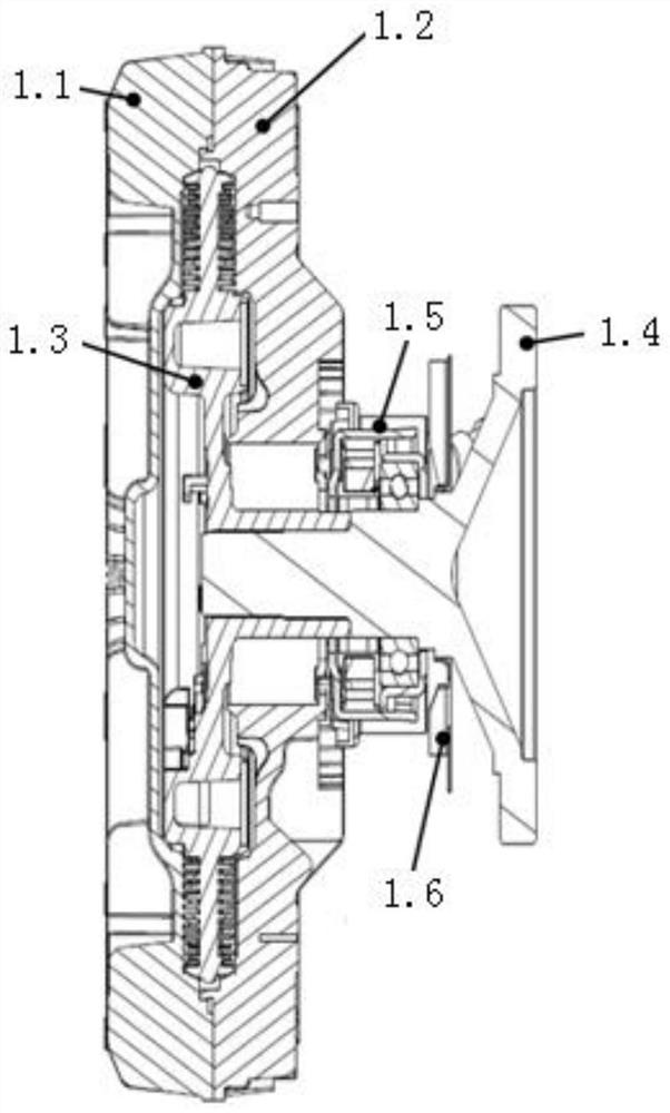
[0034] Such as figure 1 As shown, a heat dissipation silicone oil clutch of the present inven...


PUM


Abstract

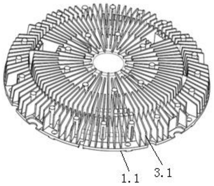
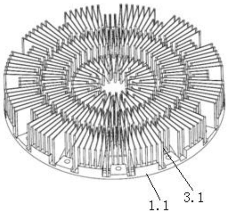
The invention relates to a heat-dissipating silicone oil clutch, which comprises a front cover, a rear cover, a driving disc, a flange shaft and an electric control solenoid, an auxiliary fan is arranged on the flange shaft, and the electric control solenoid is provided with Between the auxiliary fan and the back cover. Both the front cover and the back cover of the present invention are formed by semi-solid die-casting, and no air holes will be generated inside the front cover and the back cover, which improves the overall strength of the front cover and the back cover of the silicone oil clutch; at the same time, the metal liquid in the mold cavity during the die-casting process The flow properties are improved and the forming process is more flexible and finer. The fins adopt a multi-stage structure design, which saves materials and reduces costs compared with traditional fins; it also reduces the overall weight of the silicone oil clutch and reduces the load on the engine; at the same time, the spacing between the fins is increased to speed up the flow of air on the clutch surface. The heat dissipation performance is improved; an auxiliary fan is installed on the flange shaft for heat dissipation of the rear cover and the solenoid, which greatly reduces the possibility of failure of the silicone oil clutch due to high temperature.

Description

technical field [0001] The invention relates to an electronically controlled silicon oil fan, in particular to a heat dissipation type silicon oil clutch. Background technique [0002] The heat dissipation of the engine cooling system on the commercial vehicle platform is mainly completed by various cooling fans. The cooling fans have been upgraded from direct-connected fans that cannot be adjusted in the early stage to electromagnetic fans with adjustable speed gears, and then to silicon oil fans with infinitely variable speeds. Cooling fans are constantly developing towards more accurate speed regulation and shorter response time. Silicon oil fans currently on the market include temperature-controlled and electronically controlled silicone oil fans, among which electronically controlled silicone oil fans have become the choice of mainstream commercial vehicle platforms due to their precise control and quick response. [0003] With the introduction of National VI emissions...

Claims


Application Information

Patent Timeline
Patent Type & Authority Patents(China)
IPC IPC(8): F16D35/00F01P7/04
CPCF16D35/00F01P7/042
Inventor 彭斯王鼎吴志鹏王宁
Owner DONGFENG BEHR THERMAL SYST
Learn More