Torque amplifying device

A technology for amplifying devices and housings, which is applied to fluid pressure actuators, servo motor components, mechanical equipment, etc., can solve the problems of increased manufacturing costs, complicated processes, and high manufacturing costs, and achieve volume and weight reduction, and lower manufacturing costs. The effect of cost, adjustment and maintenance convenience

Inactive Publication Date: 2011-08-17
ZHENJIANG HYDRAULICS
View PDF7 Cites 7 Cited by
  • Summary
  • Abstract
  • Description
  • Claims
  • Application Information

AI Technical Summary

Problems solved by technology

With the compact structure of the steering device, the problems reflected in the use of this existing structure are becoming more and more prominent: first, the existing same-side distribution structure of the oil inlet and outlet makes the relief valve must be arranged axially along the torque amplification device, Once installed, the adjustment and maintenance of the relief valve is very difficult due to the limited axial space; if the relief valve is separately installed in the steering system, it will inevitably increase the manufacturing cost and cause inconvenience in installation
Secondly, the distribution of oil ports on the same side also makes it necessary to communicate with the flow distribution mechanism completely through the inclined hole, the process is complicated and the manufacturing cost is high
And cause great inconvenience to the host installation and maintenance
In addition, the existing oil port structure also makes the housing and the entire torque amplifying device bulky, which not only wastes materials, but also brings many other inconveniences

Method used


Image

  • Torque amplifying device
  • Torque amplifying device
  • Torque amplifying device

Examples


Embodiment Construction

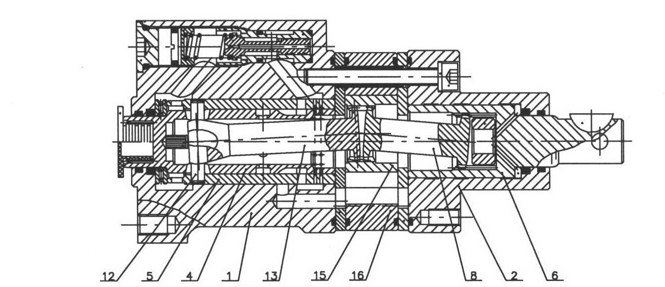
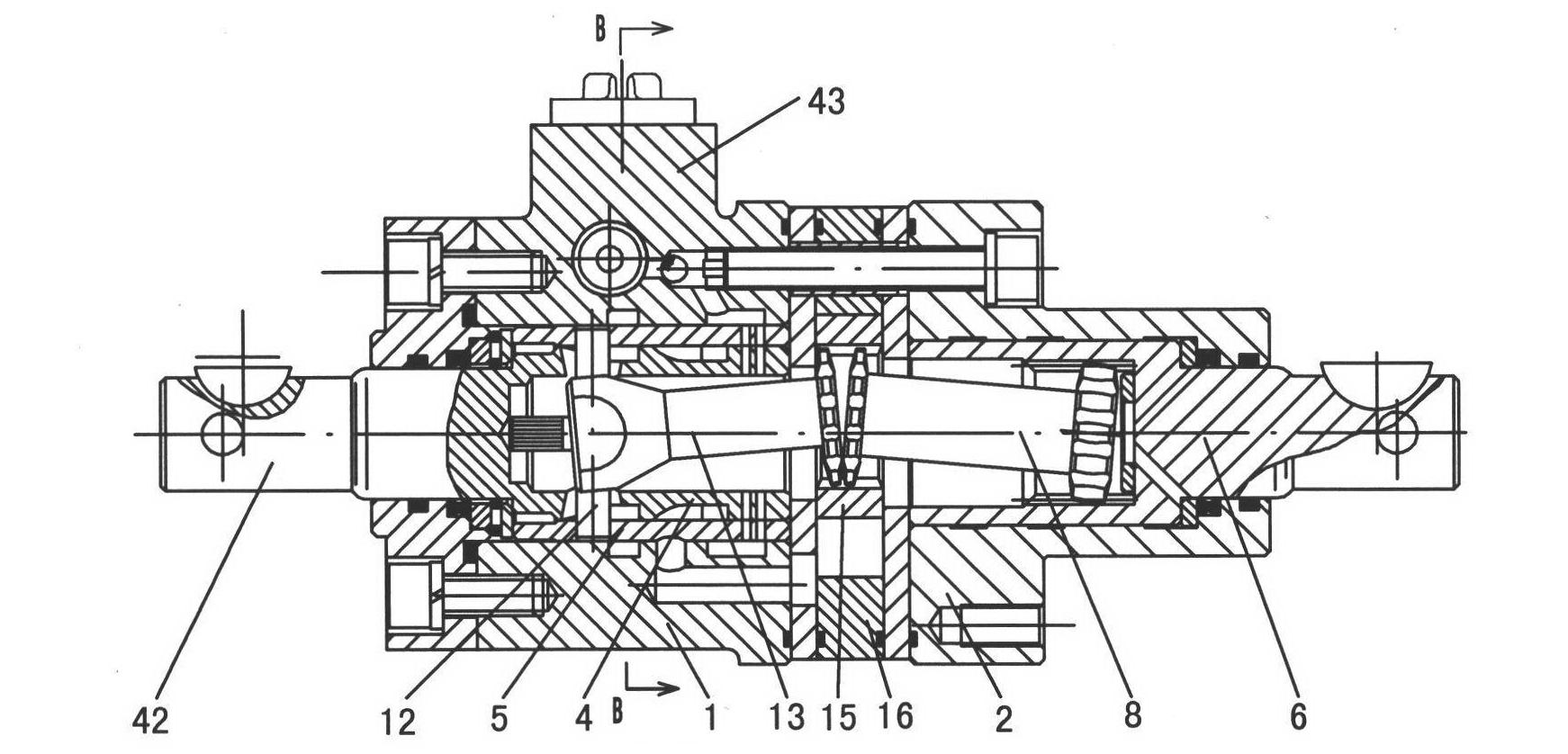
[0015] The torque amplification device of this embodiment is as Figure 2-Figure 5 As shown, there is a casing composed of a casing 1, a stator 16 and a rear cover 2 fixedly connected in sequence along the main axis direction, and two spacers are respectively installed at both ends of the stator 16. The casing 1 is provided with a spool cover 5 for the input spool 4, and the input spool 4 is connected with the input shaft 42 protruding from the casing 1 as a whole. The rotor 15 forming a cycloidal pin-wheel pair is housed in the stator 16 . The output shaft 6 is supported inside the rear cover 2 . The inner hole of the rotor 15 is engaged with the opposite ends of the input linkage shaft 13 and the output linkage shaft 8 through internal splines, and the other end of the input linkage shaft 13 is connected with the valve core sleeve 5 through the dial pin 12, and the other end of the output linkage shaft 8 One end is transmission-connected with the output shaft 6 through an ...


PUM


Abstract

The invention relates to a torque amplifying device belonging to the field of hydraulic transmission and control technology. The torque amplifying device comprises a shell, a stator and a rear cover which are fixedly connected, wherein a valve element sleeve is arranged in the shell, a rotor is arranged in the stator, an output shaft is supported in the rear cover, an inner hole of the rotor is in meshed connection with opposite ends of an input linkage shaft and an output linkage shaft simultaneously, the shell extends out of an oil port boss, the length direction of the oil port boss is vertical to the main axis of the shell, an oil inlet and an oil outlet of the shell are arranged in length direction and are respectively communicated with corresponding oil tanks in the shell through an oil inlet hole and an oil outlet hole, so as to form a flow distribution structure. An overflow valve is arranged between the oil inlet hole and the oil outlet hole, and an adjusting end of the overflow valve is arranged at one axial side surface of the oil port boss. By adopting the invention, the regulation and the maintenance are very convenient, the process is simple and the volume and the weight are reduced remarkably.

Description

technical field [0001] The invention relates to a hydraulic device, in particular to a torque amplification device, which belongs to the technical field of hydraulic transmission and control. Background technique [0002] As far as the applicant knows, the full hydraulic torque amplifying device is a traditional steering device commonly used in engineering machinery, agricultural machinery and other engineering vehicles. Its typical structure is as follows: figure 1 , 2 As shown, it includes a housing 1 fixedly connected by bolts, a flow distribution mechanism, a stator 16, and a rear cover 2. The valve core sleeve 5 is placed inside the housing, and the valve core sleeve 5 supports a valve core 4 that is fixedly connected to the input shaft. The oil inlet and outlet ports distributed on the same side of the housing 1 communicate with the oil inlet and outlet holes respectively, and communicate with the corresponding oil groove in the valve core sleeve 5 . The cycloid toot...

Claims


Application Information

Patent Timeline
IPC IPC(8): F15B13/02
Inventor 秦志文宋瑾马超张强华卢淑红
Owner ZHENJIANG HYDRAULICS
Why Eureka
Try Eureka