Internal glass finned-plate tube solar energy steam producing device

An inner glass fin tube and solar energy technology, which is applied to solar thermal devices, solar thermal energy, solar thermal power generation, etc., can solve the problems of insufficiently developed vacuum heat collector tube application products, avoid scaling problems, facilitate water withdrawal, The effect of improving performance

Inactive Publication Date: 2011-08-17
国网内蒙古东部电力有限公司赤峰供电公司 +1
View PDF4 Cites 0 Cited by
  • Summary
  • Abstract
  • Description
  • Claims
  • Application Information

AI Technical Summary

Problems solved by technology

But in general, the application products of vacuum heat collecting tubes are not rich enough.

Method used


Image

  • Internal glass finned-plate tube solar energy steam producing device
  • Internal glass finned-plate tube solar energy steam producing device
  • Internal glass finned-plate tube solar energy steam producing device

Examples


Embodiment Construction

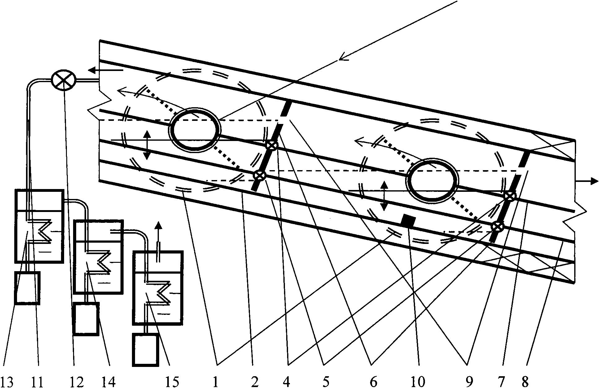
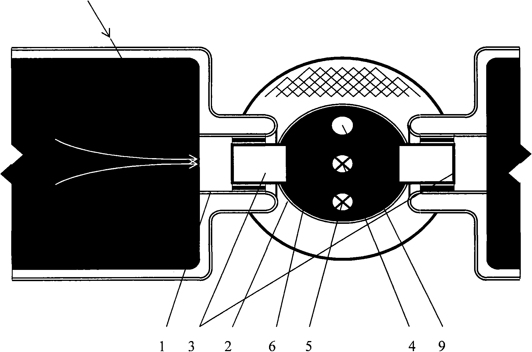
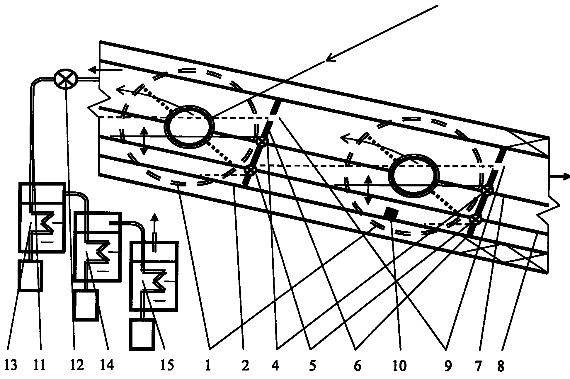
[0016] figure 1 and figure 2 An embodiment of the present invention is collectively given. figure 1 and figure 2 In the above, the heat collecting tube 1 is connected with the barges 3 on both sides of the header box 2 with sealing rings to form a horizontal vacuum heat collecting tube solar steam generating device. The heat collecting tube 1 is arranged horizontally; the collection box 2 has a casing and heat insulating material, and its axis line has a horizontal inclination angle to ensure that the light concentrating reflector can track the change of the sun's altitude angle. For the sake of brevity, the light concentrating reflector is not shown in the figure. Two multi-valve linkage electric group valves, the high group valve 4 and the low group valve 5, are used. Each valve of electric group valve 4,5 is installed on each dam 6 of multi-level cascade dam respectively, and can be opened and closed synchronously by being connected with link rod 7,8 that is connected...


PUM


Abstract

As shown in the figure, collector tubes 1 and connectors 3 at both sides of a union box 2 are connected with each other through sealing rings so as to form a horizontal solar vacuum collector tube steam production device. The collector tubes are horizontally arranged. The axis line of the union box 2 is inclined relative to the horizontal plane to ensure the angle variation of a light concentrating and reflecting device along with the height of the sun. Two multi-valve linked valve blocks, namely an electric high-altitude valve block 4 and an electric low-altitude valve block 5, are adopted. Each of all valves of the electric valve blocks 4 and 5 is respectively arranged on each of a plurality of dams of a multi-level cascade dam 6 and is connected with each other to realize the synchronous opening and closing thereof through link rods 7 and 8 of an electromagnetic valve driving mechanism. The electromagnetic valve driving mechanism is in electrical connection with a microcomputer control system. The cascade dam 6 is provided with an overflow port 9. A water temperature and water level sensor 10 in the union box 2 is in electrical connection with the host of the microcomputer control system. During the filling of water, the microcomputer control system closes the low-altitude valve block 5 and opens the high-altitude valve block 4 through the electromagnetic valve driving mechanism. Thus, raw water is obtained through a pipeline valve at the high end of the union box 2.

Description

technical field [0001] The invention relates to a solar steam generating device of an inner glass-fin plate tube. Background technique [0002] The existing vacuum heat collecting tube has high heat collecting temperature, small heat loss, and high degree of industrialization, and the intubated water heater manufactured with it can provide domestic hot water above 50°C in winter. But in general, the application products of vacuum heat collecting tubes are not rich and developed enough. Contents of the invention [0003] The object of the present invention is to provide a solar steam generating device with inner glass-fin plate tube. [0004] The technical scheme adopted by the present invention to solve the technical problem: use the inner glass-fin plate tube and the union box matched and connected with the inner glass-fin plate tube to form an inner glass-fin plate tube solar steam generating device. The inner glass tube of the inner glass-finned tube has metal fins, a...

Claims


Application Information

Patent Timeline
IPC IPC(8): F22B1/00F24J2/05F24S10/40
CPCY02E10/44
Inventor 陈旭
Owner 国网内蒙古东部电力有限公司赤峰供电公司
Why Eureka
Try Eureka