
Electric leakage detection and protection circuit

A protection circuit, leakage detection technology, applied in the direction of emergency protection circuit device, circuit device, emergency protection device with automatic disconnection, etc.

Inactive Publication Date: 2011-08-17
黄华道
View PDF4 Cites 2 Cited by
  • Summary
  • Abstract
  • Description
  • Claims
  • Application Information

AI Technical Summary

Problems solved by technology

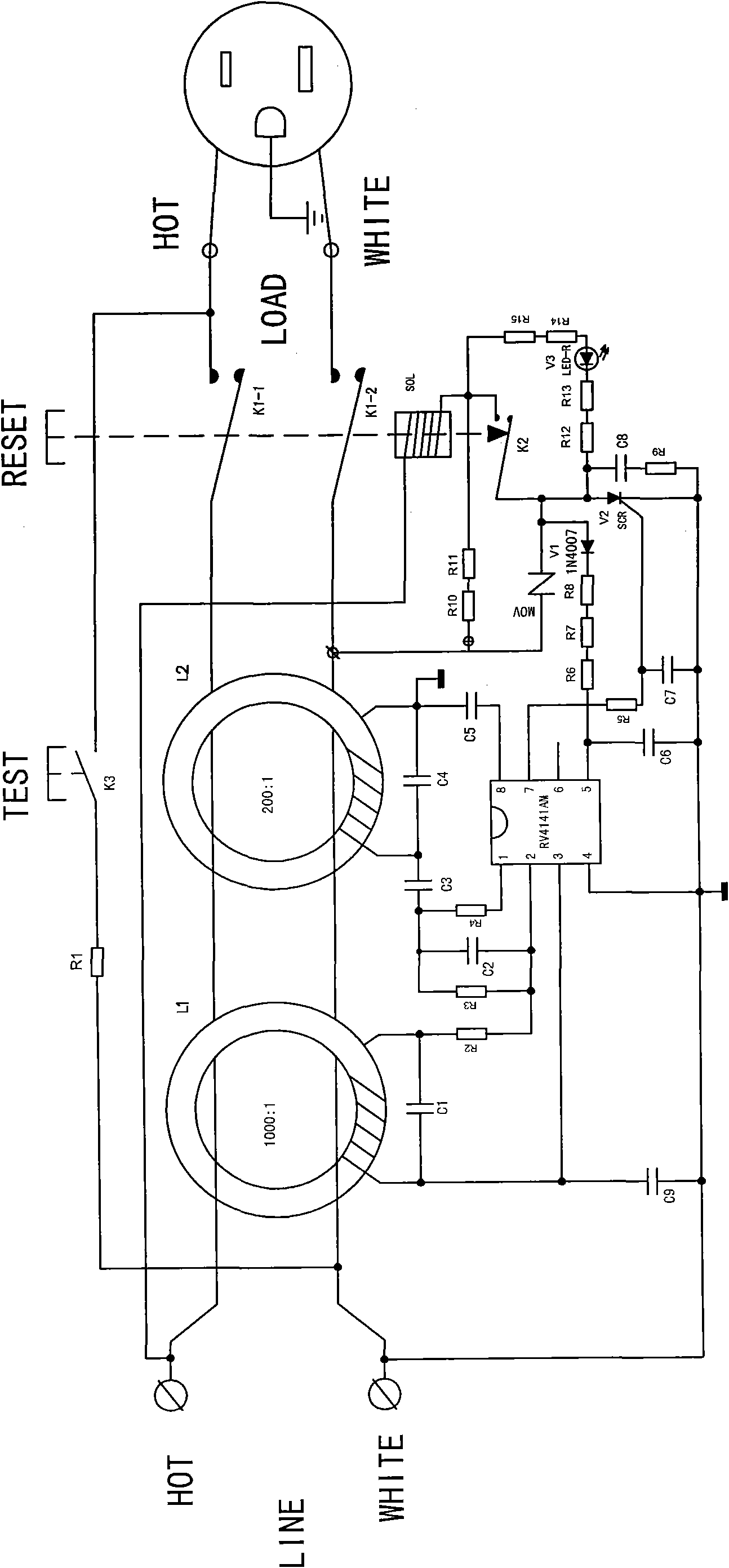
[0004] but, figure 1 The leakage detection protection circuit shown also has a fatal shortcoming: when the power input terminal of the leakage detection protection circuit is connected to the live wire and the neutral wire of the power supply, within a few seconds of generating the analog leakage current, the current limiting resistor used to generate the analog leakage current R10 and R11 were burned
[0006] In summary, figure 1 The safety of the leakage detection protection circuit shown is flawed

Method used


Image

  • Electric leakage detection and protection circuit
  • Electric leakage detection and protection circuit
  • Electric leakage detection and protection circuit

Examples


Embodiment Construction

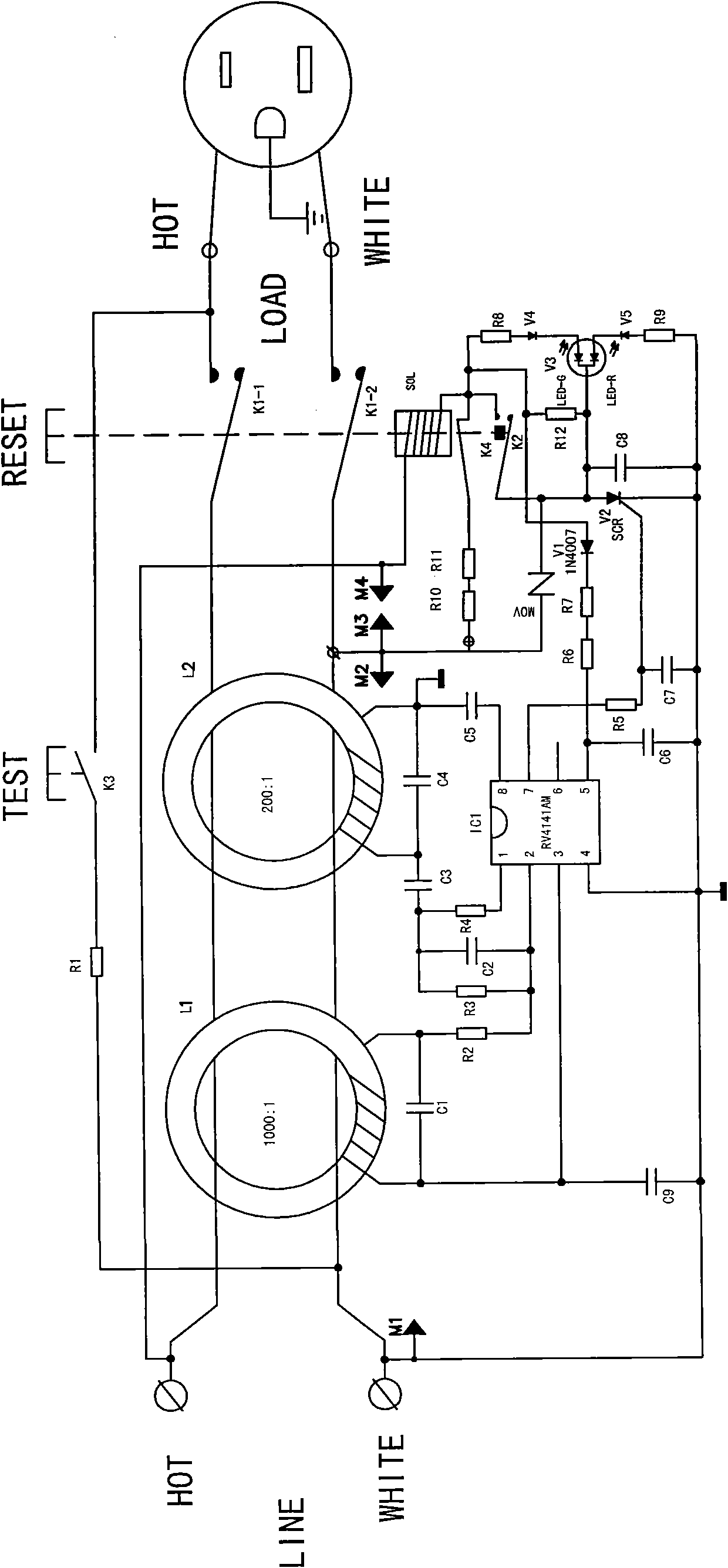
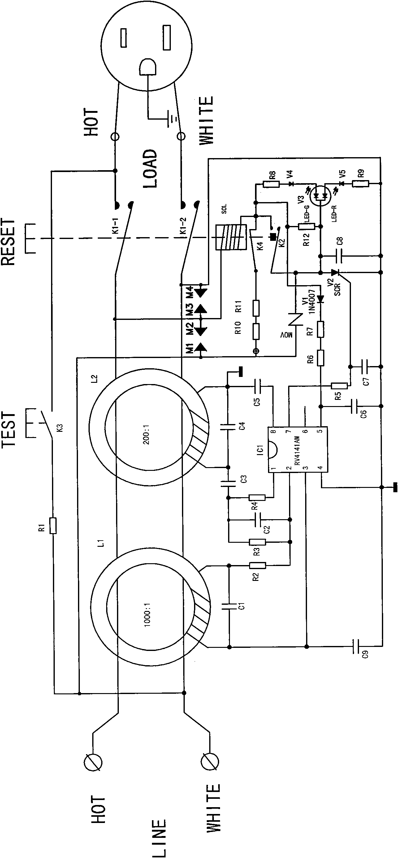
[0036] Such as figure 2 As shown, the leakage detection and protection circuit disclosed in the present invention mainly includes an induction coil L1 for detecting leakage current, a self-excited coil L2 for detecting low-resistance faults, a control chip IC1 (model RV4141AM), and a tripping circuit with a built-in iron core. Coil SOL, thyristor V2, end-of-life detection switch K4 controlled by the electromagnetic lock mechanism, lock switch K2, and main circuit switches K1-1 and K1-2 linked with the reset button. When the reset button RESET is in the tripping state, the end-of-life detection switch K4 is closed, and the lock switch K2 is turned off; when the reset button RESET is reset, the end-of-life detection switch K4 is turned off, and the lock switch K2 is closed.

[0037]The live wire and neutral wire of the power input terminal LINE pass through the induction coil L1 for detecting leakage current, the self-excited coil L2 for detecting low-resistance faults, the mai...


PUM


Abstract

The invention discloses an electric leakage detection and protection circuit which is characterized by comprising an end-of-life detection switch, controlled by an electromagnetic latching mechanism, and a latching switch. An anode of a thyristor is connected with a live line of a power input end through the latching switch and a trip coil, and an iron core is embedded in the trip coil; a cathode of the thyristor is connected with a zero line of the power input end; the end-of-life detection switch and a current-limiting resistor are serially connected to form a simulated leakage current generating circuit for completing an end-of-life detection function; and one end of the simulated leakage current generating circuit is connected with the zero line of the power input end passing through an induction coil and a self-excitation coil, and the other end is connected with the live line of the power input end through the trip coil. When a reset button is tripped, the end-of-life detection switch is closed, and the latching switch is off; when the reset button is reset, the end-of-life detection switch is off, and the latching switch is on; and when the reset button is pressed, the latching switch is on, and the end-of-life detection switch is off.

Description

technical field [0001] The invention relates to a circuit with leakage detection, display and protection functions installed in a power plug, a power socket or a power switch with the leakage protection function. Background technique [0002] With the continuous development of the power socket with leakage protection function (referred to as GFCI), power plug, and power switch industry, people have higher and higher requirements for the function and safety of power socket with leakage protection function, power plug, especially Power sockets, power plugs exported to the United States. The United States requires that the power sockets and power plugs exported to the United States must have the end-of-life detection function. Before use, the power sockets and power plugs must be self-tested. When their life ends, the reset buttons on the power sockets and power plugs must never be reset. , The power socket and power plug have no power output. This makes people in the industr...

Claims


Application Information

Patent Timeline
Patent Type & Authority Applications(China)
IPC IPC(8): H02H3/32G01R31/02
Inventor 黄华道
Owner 黄华道
Learn More