Motor rotor

A motor rotor and rotor shaft technology, applied in the direction of asynchronous induction motors, electric components, electrical components, etc., can solve the problems of high production cost, low work efficiency, manual work, etc., and achieve reduced production costs, high work efficiency, and guaranteed performance effect

Inactive Publication Date: 2011-08-17
王文扬
View PDF5 Cites 13 Cited by
  • Summary
  • Abstract
  • Description
  • Claims
  • Application Information

AI Technical Summary

Problems solved by technology

This structure has the following disadvantages: First, it adopts welding connection. During the welding process, the rotor needs to be heated to a certain temperature to meet the welding process requirements, so that the copper guide bar and the copper end ring have a good welding force, or A large amount of heat is generated during the welding process, which causes the rotor punch to be overheated and affects the performance of the motor. The shape of the guide bar changes, and the process is complicated; the third is that welding is manual, the process is complicated, and the work efficiency is low; the fourth is that copper end rings are used on high-power motors, and the production cost is high.

Method used


Image

  • Motor rotor
  • Motor rotor
  • Motor rotor

Examples


Embodiment Construction

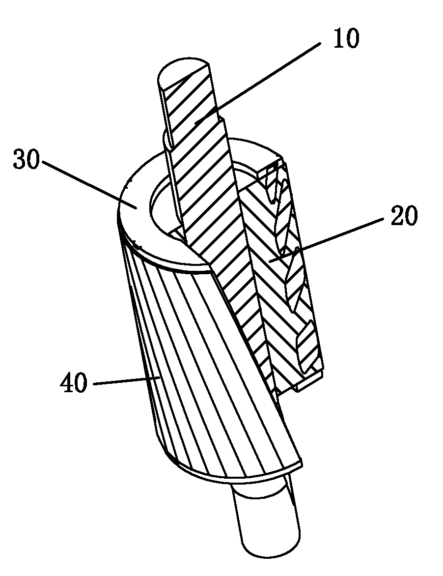
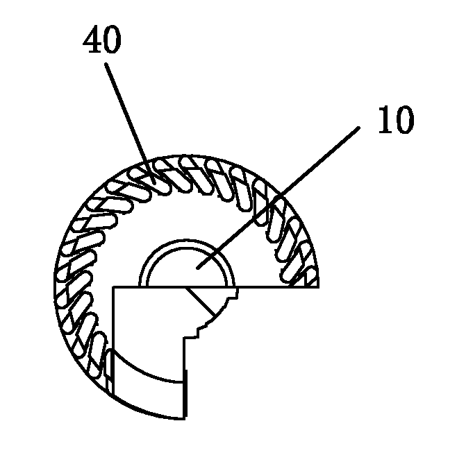
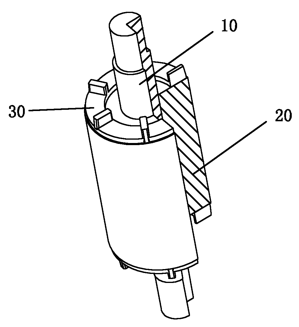
[0023] The present invention will be further described below with specific embodiment, see Figure 1-6 :

[0024] The rotor of the motor is formed by a rotor core 20 outside the rotor shaft 10, and end rings 30 are arranged at both ends of the rotor core 20. The rotor core 20 is formed by stacking several rotor punches. There is a circle of evenly distributed guide bar holes on the rotor punch. The guide bar holes on the rotor punch form a circle of guide bar grooves on the circumferential surface of the rotor iron core 20 after the rotor punches are stacked. A copper guide bar 40 is provided, and the two ends of the rings 30 and the two ends of the copper guide bar 40 are die-casted integral structures or connected by riveting. The one-piece structure of die-casting is instantly formed, which has little impact on the rotor punching, and the rotor does not produce overheating reaction, which ensures the performance of the motor, improves production efficiency, and reduces pro...


PUM


Abstract

The invention relates to a motor rotor. A rotor iron core is sleeved outside a rotor shaft; both ends of the rotor iron core are provided with end rings; the rotor iron core is formed by laminating a plurality of rotor punching sheets; a circle of uniformly distributed guide strip holes are arranged in the rotor punching sheets; the guide strip holes in the rotor punching sheets form a circle of guide strip groove positioned on the circumference surface of the rotor iron core after the rotor punching sheets are laminated; copper guide strips are tightly configured in the guide strip groove; and the two end rings and both ends of the copper guide strips form a die-casting integral type structure or riveting connection. By using the motor rotor, the performance of a motor can be ensured, simple process and high working efficiency can be achieved and the production cost can be reduced.

Description

Technical field: [0001] The invention relates to a motor rotor. Background technique: [0002] Motor refers to an electromagnetic device that realizes the conversion or transmission of electric energy according to the law of electromagnetic induction, including a stator and a rotor. At present, cast copper rotors are usually used, and copper casting is performed in the guide slots formed by stacking the rotor punches, which can reduce the current loop loss and improve the efficiency of the motor. However, there are disadvantages such as poor process stability, easy generation of air bubbles and other phenomena that affect the performance of the motor, and high production costs. In order to improve this phenomenon, copper guide bars are arranged in the guide bar grooves formed by stacking the rotor punching sheets, and end rings are arranged at both ends of the copper guide bars. For example, the motor rotor disclosed in Patent No. 200920141813. Copper guide bars are embedd...

Claims


Application Information

Patent Timeline
Patent Type & Authority Applications(China)
IPC IPC(8): H02K1/26H02K3/50
CPCH02K17/205H02K17/20
Inventor 王文扬
Owner 王文扬
Why Eureka
Try Eureka