

Backflow prevention device, electronic apparatus, and method for producing backflow prevention device
A backflow prevention device, technology for electronic equipment, applied in the direction of electrical equipment structural parts, electrical components, electrical digital data processing, etc., can solve the problems of increasing the number of manufacturing steps, errors, etc.
- Summary
- Abstract
- Description
- Claims
- Application Information
AI Technical Summary
Problems solved by technology
Method used
Image

Examples
no. 1 approach
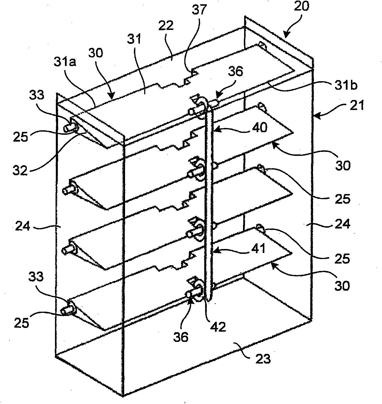
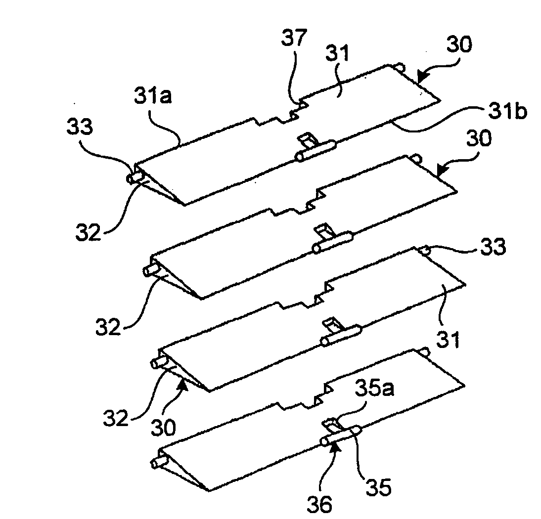
[0088] The backflow prevention device, electronic equipment, and method for manufacturing the backflow prevention device disclosed herein will now be described in more detail with reference to the accompanying drawings according to preferred embodiments. figure 1 is a view illustrating the inside of the backflow prevention device according to the first embodiment. figure 2 is a perspective view illustrating the shape of the flap of the backflow preventer.
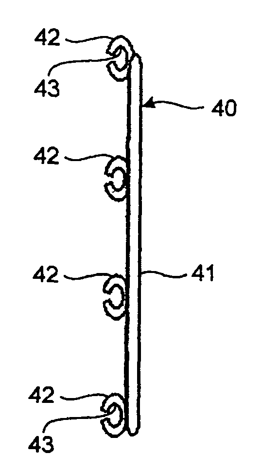
[0089] image 3 is a perspective view illustrating the shape of the connection member. Figure 4A , 4B and 4C are perspective views illustrating flaps open, flaps closed, and flaps half-opened, respectively. also, Figure 5A is a perspective view illustrating the configuration of an electronic device according to an example of the first embodiment. Figure 5B is a block diagram illustrating the configuration of an electronic device according to an example of the first embodiment. It should be noted that in the backfl...
no. 2 approach
[0110] A backflow prevention device will be described according to an example of the second embodiment. Figure 6 is a view illustrating the inside of the backflow prevention device according to an example of the second embodiment. Figure 7 is a perspective view illustrating the shape of the flap of the backflow preventer.
[0111] also, Figure 8 is a perspective view illustrating the shape of the connection member. Figure 9A , 9B 9C and 9C are perspective views illustrating flaps open, flaps closed, and flaps half-opened, respectively. It should be noted that in the backflow prevention device according to the example of the second embodiment, the same components as those of the above-described first embodiment are denoted by the same symbols and descriptions will not be repeated.
[0112] Structure of the backflow prevention device 20a
[0113] Such as Figure 6 As illustrated in , the backflow prevention device 20a includes a plurality of flaps 30a in the frame box ...
no. 3 approach
[0128] A backflow prevention device according to an example of the third embodiment will be described. Figure 10 is a view illustrating the inside of the backflow prevention device according to the third embodiment. Figure 11 is a perspective view illustrating the shape of the connection member. Figure 12A , 12B 12C and 12C are perspective views illustrating flaps open, flaps closed, and flaps half-opened, respectively.
[0129] It should be noted that in the backflow prevention device according to the example of the third embodiment described below, the components of the backflow prevention device that are the same as those of the backflow prevention device according to the example of the second embodiment described above are denoted by the same symbols and not repeated. Describe repeatedly.
[0130] Structure of backflow prevention device 20b
[0131] Such as Figure 10 As illustrated in , the backflow prevention device 20b includes a plurality of flaps 30a disposed ...
PUM
 Abstract
Description
Claims
Application Information