Welding supporting table for joints

A support table, rectangular technology, applied in welding equipment, auxiliary welding equipment, welding/cutting auxiliary equipment, etc., can solve the problems of low operation efficiency, complex structure, high cost, achieve firm and stable support, improve support strength, realize Efficiency effect

Active Publication Date: 2011-08-24
KOBE STEEL LTD
View PDF10 Cites 5 Cited by
  • Summary
  • Abstract
  • Description
  • Claims
  • Application Information

AI Technical Summary

Problems solved by technology

[0006] The existing rotary positioner cannot be used with the conventional joint welding device, and a dedicated positioner needs to be remanufactured
In addition, a transposer is required for one joint, and the structure is also very complicated, so that the cost is too high relative to the welding work for one joint, and there is also a problem that each joint must be fixed and welded. Operation, disassembly operation, so the operation efficiency is not high
[0007] In addition, the conventional welding equipment for joints does not use the existing rotary positioner, so there is a problem that it uses a special equipment for joint welding, and it is necessary to secure its use place.

Method used


Image

  • Welding supporting table for joints
  • Welding supporting table for joints
  • Welding supporting table for joints

Examples


Embodiment Construction

[0036] Hereinafter, embodiments of the present invention will be described in detail with reference to the drawings.

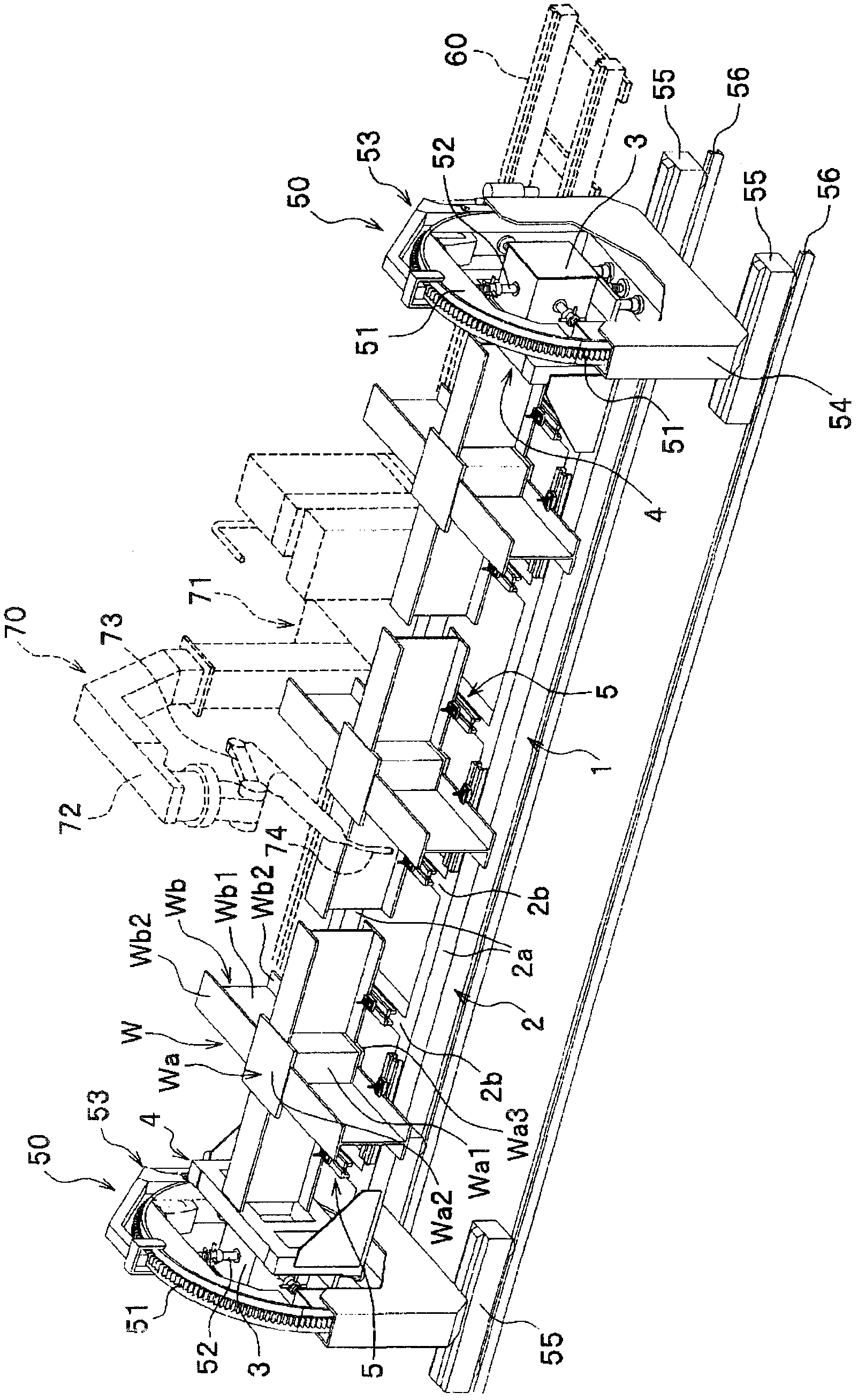
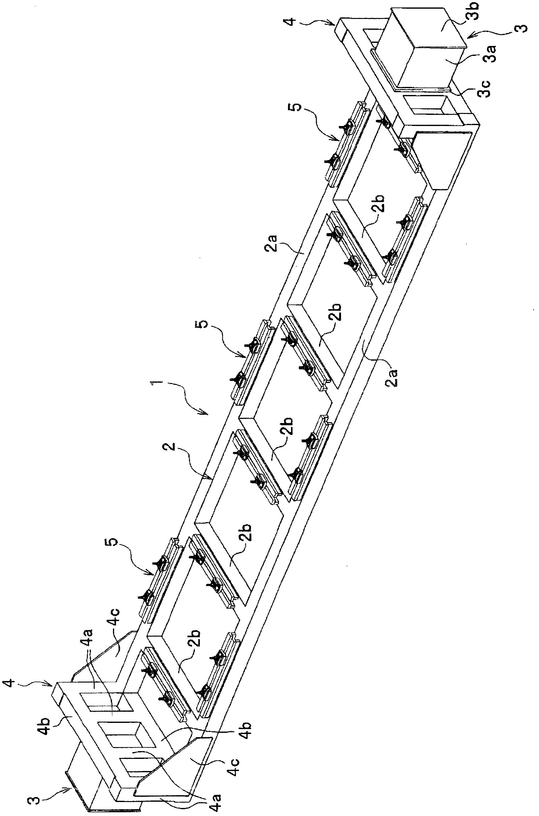
[0037] Such as figure 1 As shown, the joint welding support table 1 supports a plurality of (here, three) joints W, and is held between existing rotary positioners 50 and 50 for use. In addition, a conventional welding device 70 is installed along a direction straddling between the rotary indexers 50 and 50 .

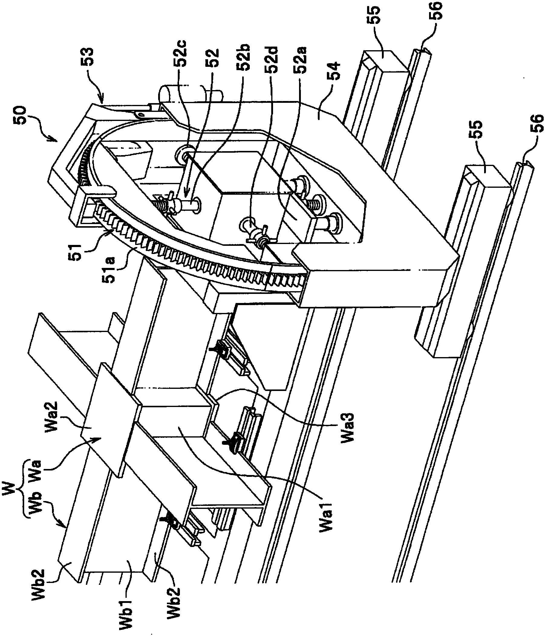
[0038] The rotary positioner 50, 50 is a device with a conventional structure, holds the welding support table 1 for a workpiece or a joint as a welding object, and moves the held workpiece or welding support table 1 for a joint from The basic position is rotated by a predetermined angle or moved on the moving rail 56 for a positioner, and the welding support table 1 for workpieces or joints is moved in a sliding manner. Also, the composition of the rotary transposer 50, 50 is as follows: figure 1 As shown, the fixing jig 52 held from four sides towa...


PUM


Abstract

The invention relates to a welding supporting table for joints, the welding supporting table freely detachably supports joints formed by connection of a beam installation part and a wall surface of a joint core plate in spot welding, thereby keeping the joint at a pair of rotary transposers, the welding supporting table comprises: a mounting part disposed at a position between the pair of rotary transposers in a mode that a plurality of joints are mounted on a same plane; a supporting mechanism disposed on the mounting part and performing support of the beam installation part of the joints; a column-shaped part respectively disposed at two ends of the mounting part, and kept in a free detachable way via fixed clamping tools disposed at the inner sides of annular parts of the rotary transposers. According to the composition, joint positioning of current rotary transposers can be easily performed, a plurality of joints can welded, and original welding operation zones of the rotary transposers can be effectively used.

Description

technical field [0001] The invention relates to a joint welding supporting table which can use the existing rotary positioner to complete the joint welding operation. Background technique [0002] Generally, columns for steel frames such as upright columns, SRC columns, and round pipe columns of steel frame buildings are manufactured by welding joints prepared in advance and long column materials to form a continuous structure in the longitudinal direction. Moreover, when carrying out the welding operation of the column for steel frame, a pair of rotary positioners are used, and the two end parts of the column for steel frame are held on the rotary positioner, and the steel structure column can be moved along the length direction of the column for steel frame. welding equipment for this task. [0003] For this reason, the welding of steel frame columns needs to be prepared by making joints first. The joints used here are usually welded a circle of cross-sectional plates (p...

Claims


Application Information

Patent Timeline
Patent Type & Authority Applications(China)
IPC IPC(8): B23K37/047
Inventor 定广健次
Owner KOBE STEEL LTD
Why Eureka
Try Eureka