Mounting structure of lighting device

A lighting device and installation structure technology, applied in transportation and packaging, bicycle accessories, optical signals, etc., can solve the problems of difficult maintenance, reduced appearance, no blur, etc., and achieve the effect of excellent appearance

Active Publication Date: 2011-08-24
HONDA MOTOR CO LTD
View PDF7 Cites 4 Cited by
  • Summary
  • Abstract
  • Description
  • Claims
  • Application Information

AI Technical Summary

Problems solved by technology

[0005] Utilizing the drainage passage arrangement disclosed in Patent Document 1 to provide a passage connecting the inside and outside of the taillight device, the inner surface of the lens of the taillight device can be prevented from being blurred. Drain the water and make the water along the surface of the rear fender, reducing the appearance
Therefore, it is considered that the passage connecting the inside and outside of the taillight device passes through the inner side (reverse side) of the rear fender. Although this structure improves the appearance, water splashed from the rear wheel is easy to enter through the passage, and it is difficult to maintain the function of not blurring.

Method used


Image

  • Mounting structure of lighting device
  • Mounting structure of lighting device
  • Mounting structure of lighting device

Examples


Embodiment Construction

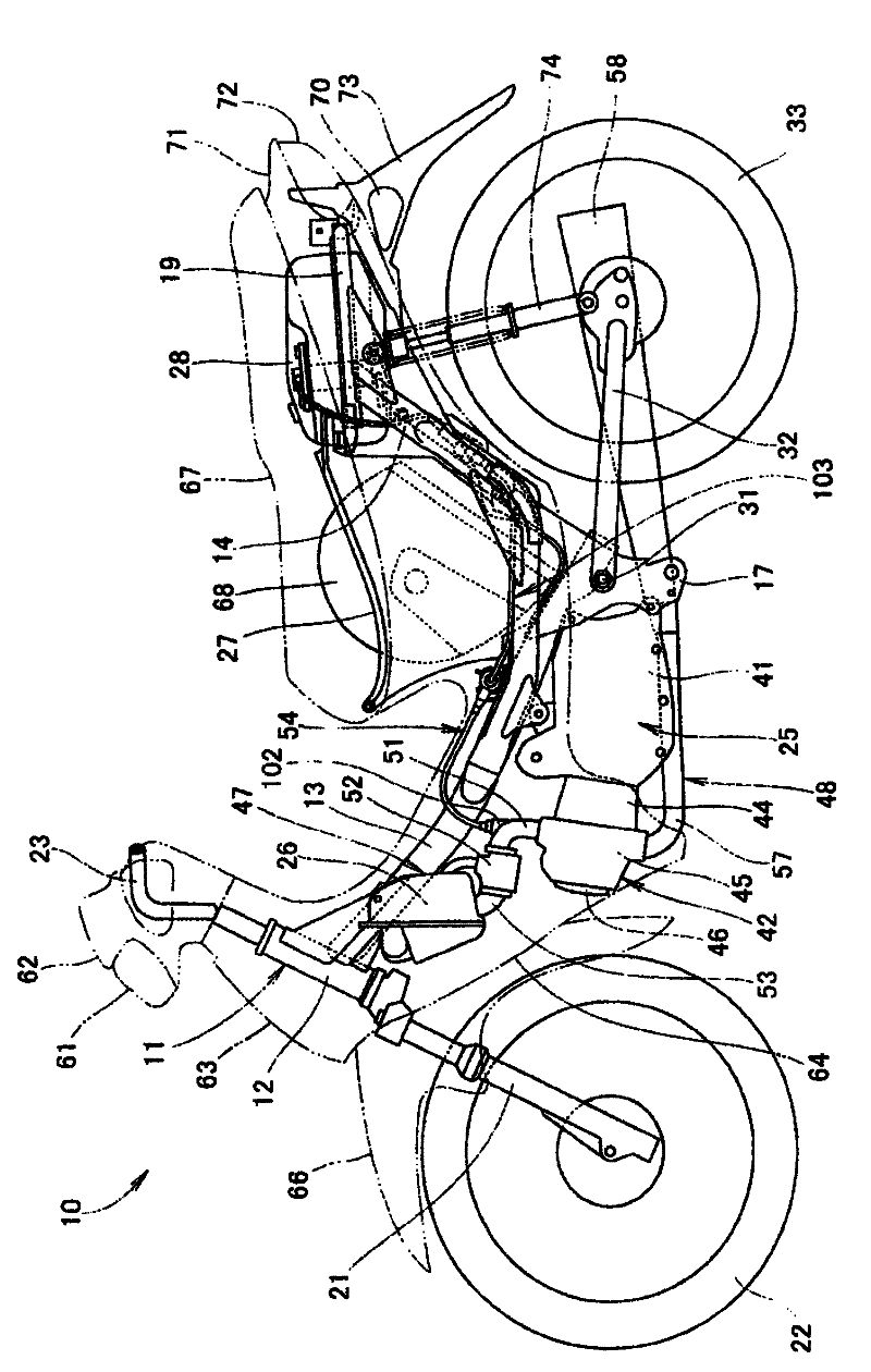
[0044] Hereinafter, preferred embodiments of the present invention will be described in detail with reference to the accompanying drawings. Left, right, front, and rear in the description are directions expressed based on the driver of the vehicle. An arrow (FRONT) in the figure indicates the front of the vehicle.

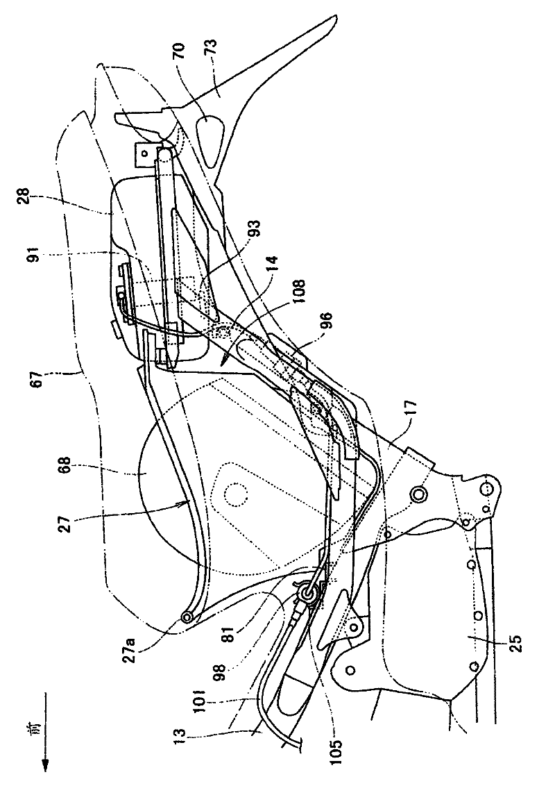
[0045] figure 1 It is a side view of a motorcycle 10 to which a lighting device mounting structure according to an embodiment of the present invention is applied. figure 2 yes figure 1Enlarged view of the rear side of the car body. The motorcycle 10 is provided with a body frame 11 serving as a main frame. The body frame 11 includes a head pipe 12 constituting a front end, a main frame 13 extending diagonally downward from the head pipe 12, and a A pair of left and right rear frames 14 extending from the middle part of the frame 13 to the rear and pointing obliquely upward, and a pair of left and right pivot plates 17 attached to the left and right rear ends o...


PUM


Abstract

The invention provides a mounting structure of a lighting device, wherein a pathway communicating the internal and external of a lamp body is arranged at the inner side of a rear mudguard, so that the pathway is not affected by the water splashed from the trailing wheel. A signal lamp device (70) equipped with a vent (79) at the base (75) of a bearing lamp support (80) is arranged on the outer side of the rear mudguard (73) of a two-wheel motor vehicle (10). The inner end portions of the lamp socket (80) and the vent (79) are arranged on the rear mudguard (73) facing the inner side of the vehicle body by the signal lamp device (70). The inner side of the rear mudguard (73) is equipped with a protection wall (84) formed integrally with the rear mudguard (73) for enclosing the periphery of the opening part (73e). The bottom wall (84d) of the protection wall (84) is equipped with a drainage hole (86). The drainage hole (86) is arranged close to the front end and the inner side of the vehicle body on the bottom wall (84d).

Description

technical field [0001] The present invention relates to a lighting device installation structure, and in particular to a lighting device installation structure for installing a lighting device on a rear fender of a two-wheeled motor vehicle. Background technique [0002] Conventionally, there is known a structure in which a lighting device is attached to a rear fender covering the rear wheels of a motorcycle from above to the rear. [0003] In the lighting device mounting structure disclosed in Patent Document 1, a tail light device serving as a license plate light is mounted on the surface of the rear fender on the rear side of the vehicle body, and the moisture accumulated in the license plate lens portion formed with a concave portion on the upper part of the tail light device passes through the inside of the tail light device. Exhaust from the lower part of the tail light unit. [0004] Patent Document 1: (Japanese) Patent No. 3608369 [0005] Utilizing the drainage pa...

Claims


Application Information

Patent Timeline
Patent Type & Authority Applications(China)
IPC IPC(8): B62J6/00B62J6/04B62J15/00
CPCB62J6/00B62J6/04B62J15/00
Inventor 石见修吾中陈诚
Owner HONDA MOTOR CO LTD
Why Eureka
Try Eureka