
Multi-functional constant flow control valve

A control valve, constant flow technology, applied in the direction of functional valve type, safety valve, balance valve, etc., can solve the problems of difficult disassembly and maintenance, complex structure, etc., and achieve the effect of reducing maintenance time and failure rate.

Inactive Publication Date: 2011-08-24
北京天箭星节能技术有限公司 +1
View PDF4 Cites 12 Cited by
  • Summary
  • Abstract
  • Description
  • Claims
  • Application Information

AI Technical Summary

Benefits of technology

This new technology improves upon existing systems by allowing for more precise temperature measurement while controlling fluid flows accurately through an electric or hydraulic circuit. Its technical effect lies within this innovation: it provides better functionality than current methods like thermometers without requiring manual intervention from users who are responsible for maintaining accurate measurements over longer periods of use; makes it easier to install and service multiple types of equipment due to its versatile design, making them suitable for different applications such as water supply networks.

Problems solved by technology

This patented technology describes an improved system for controllably deliver fluids with equal levels or evenly distributed across multiple pipelines connected together without changing their direction during operation.

Method used


Image

  • Multi-functional constant flow control valve
  • Multi-functional constant flow control valve
  • Multi-functional constant flow control valve

Examples


Embodiment Construction

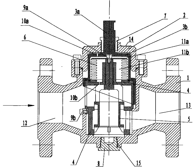
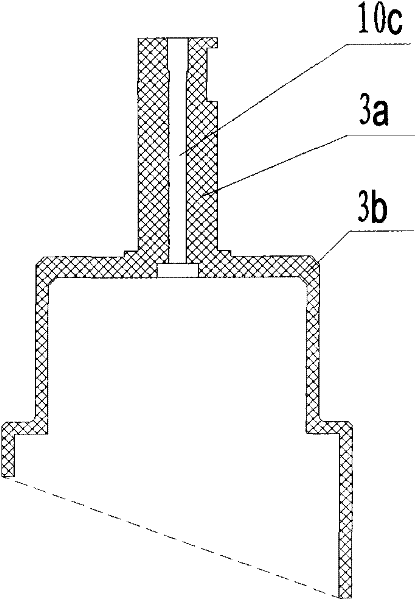
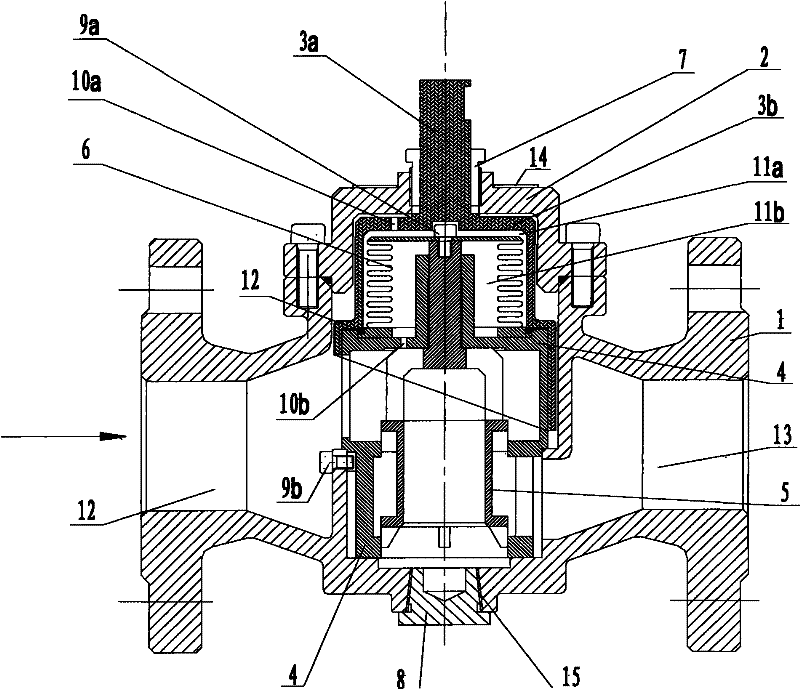
[0017] A multifunctional constant flow regulating valve for fluid regulation and automatic control, including a valve body 1, a valve cover 2 is installed on the valve body 1, a valve shaft 3a, a regulating valve disc 3b, a double-seat valve disc 5, and a valve body 1 are installed in the valve body 1. Cover 4, differential pressure sensor 6. The bonnet 2 presses the pressure flange 7 to adjust the valve disc 3b to achieve positioning. The bonnet 2 is connected to the valve body through the flange, and the bonnet is tightly fixed on the valve body through the ring-shaped sealing boss on the inner side of the lower part of the flange and the sealing ring. On the valve body, and ensure a good sealing effect. The valve shaft 3a can be rotated by different actuators to change the opening degree of the regulating disc to adjust the flow rate. There is a dial 14 on the valve cover 2 to display the flow value.

[0018] In this embodiment, the pressure difference sensor 6 is sealed a...


PUM


Abstract

The invention relates to a multi-functional constant flow control valve used for flow adjustment and automatic control. The multi-functional constant flow control valve includes a valve body which is provided with a valve cover at the upper portion and a sewage draining exit at the lower portion. The valve cover is provided with a valve shaft at the center. The valve shaft is provided with an adjusting valve clack at the lower portion. A valve pocket, a differential pressure receptor and a bi-seat valve clack with a function of compensating the differential pressure are arranged inside the valve body. The valve pocket, the differential pressure receptor and the bi-seat valve clack with the function of compensating the differential pressure constitute a valve core. Compared with the prior art, the multi-functional constant flow control valve is more reasonable and compact in structure, simple in disassemble and maintenance, visual in flow display, and abundant in function, thus being applicable to more fields.

Description


Claims


Application Information

Patent Timeline
Owner 北京天箭星节能技术有限公司
Learn More