
Hydraulic-disassembly cylindrical interference connection structure and assembly/disassembly method

A cylindrical surface and hydraulic technology, applied in metal processing, metal processing equipment, manufacturing tools, etc., can solve the problem that the cylindrical surface should not be disassembled many times, and achieve the effect of novel structure, protection of the joint surface, and avoidance of scratches.

Inactive Publication Date: 2012-09-19
SHANGHAI MEISHAN IRON & STEEL CO LTD
View PDF1 Cites 7 Cited by
  • Summary
  • Abstract
  • Description
  • Claims
  • Application Information

AI Technical Summary

Problems solved by technology

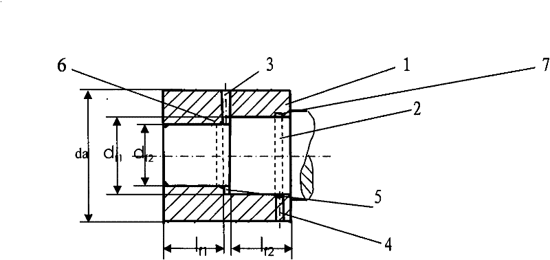
[0004] The purpose of the present invention is to provide a structure and method for hydraulically dismantling the interference connection of a cylindrical surface that can be easily disassembled multiple times: mainly to solve the problem that the existing cylindrical surface interference connection is not suitable for multiple disassembly and requires a large press for disassembly technical problem

Method used


Image

  • Hydraulic-disassembly cylindrical interference connection structure and assembly/disassembly method
  • Hydraulic-disassembly cylindrical interference connection structure and assembly/disassembly method

Examples


Embodiment Construction

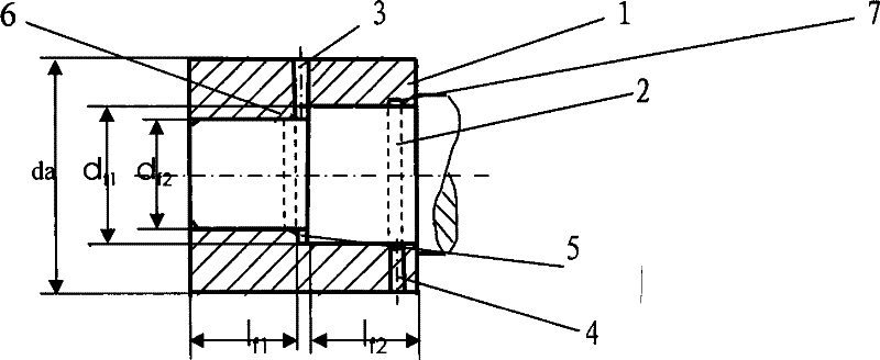
[0019] refer to figure 1 , a structure for hydraulically dismantling cylindrical surface interference connections, consisting of a containing part 1 and a contained part 2, the containing part 1 is a stepped inner cylindrical hole, and the contained part 2 is a stepped outer cylindrical shaft matching the shape of the containing part, containing Part 1 and contained part 2 cooperate with the distance between the shoulder end faces to form a hydraulic oil chamber 5. The containing part 1 is provided with a dismounted hydraulic oil inlet hole 3 that communicates with the hydraulic oil chamber 5. When the containing part or the contained part matches the shoulder There is a lubricating oil groove on one side of the end face.

[0020] The step of the ladder is set at the bisection of the matching length, so that the matching lengths of the two cylindrical surfaces are equal. The distance between the hydraulic oil cavity between the matching shoulder end surface of the containing ...


PUM


Abstract

The invention relates to a cylindrical interference connection structure and an assembly / disassembly method, in particular to a hydraulic-disassembly cylindrical interference connection structure and an assembly / disassembly method, aiming to solve such technical problems that existing cylindrical interference connection is not suitable for repeated disassembly and that a large-sized press machine is required for disassembly. The hydraulic-disassembly cylindrical interference connection structure comprises an accommodating member and an accommodated member, wherein the accommodating member is of stepped inner cylindrical hole form, the accommodated member is a stepped outer cylindrical shaft matching with the accommodating member in shape, the spacing between the matching shoulder end faces of the accommodating member and the accommodated member forms a hydraulic oil cavity, the accommodating member is provided with a disassembly hydraulic oil inlet hole communicating with the hydraulic oil cavity, and a lubricating oil way is formed at one side of the matching shoulder end face of the accommodating or accommodated member. In assembly, a temperature difference method is adopted; and in hydraulic disassembly, a high pressure oil pump supplies high pressure lubricating oil to between the matching surfaces of the accommodating member and the accommodated member to form an oil film, high pressure hydraulic oil is pumped into the hydraulic oil cavity, and pressure intensity of the high pressure hydraulic oil acts on the stepped cylindrical shaft and hole shoulder end faces to apply axial hydraulic thrust in opposite directions to the accommodating member and the accommodated member, to enable the accommodating member and the accommodated member to slide and further separate from each other. The inventive structure is suitable for connection between a large-sized shaft coupling and a shaft.

Description

technical field [0001] The invention relates to a structure and a loading and unloading method of a cylindrical surface interference connection, in particular to a structure and a loading and unloading method of a hydraulically dismantled cylindrical surface interference connection. The structure is suitable for the connection between a large shaft coupling and a shaft. Background technique [0002] The interference fit connection currently has a cylindrical surface interference fit connection and a conical surface over-win connection. The cylindrical surface interference connection is disassembled by a high-pressure oil lubrication press, and the conical surface over-win connection is disassembled by hydraulic pressure. [0003] There have been large-scale cylindrical surface interference fit connections. When the interference and fit size are large, the temperature difference method is often used for assembly. During the disassembly process, the mating surface will be scra...

Claims


Application Information

Patent Timeline
IPC IPC(8): B23P19/027
Inventor 杨赛昕蔡强
Owner SHANGHAI MEISHAN IRON & STEEL CO LTD
Learn More